EE-SPY411 Omron, EE-SPY411 Datasheet - Page 4
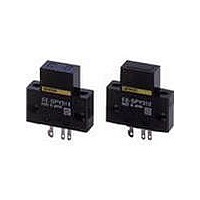
EE-SPY411
Manufacturer Part Number
EE-SPY411
Description
Photomicrosensors CONV REFL LIGHT-ON
Manufacturer
Omron
Series
-r
Specifications of EE-SPY411
Output Configuration
Light-On
Sensing Distance
2 mm to 6 mm
Sensing Method
Reflective
No. Of Pins
4
Opto Case Style
Module
No. Of Channels
1
Operating Temperature Range
-10°C To +55°C
Operating Voltage Max
24VDC
Operating Voltage Min
5VDC
Output Current Max
80mA
Proximity Sensor Type
Optical
Output Type
PNP
Proximity Sensor Sensing Distance
5mm
Proximity Sensor Sensing Distance Range
2 to 7mm
Proximity Sensor Switching Mode
Light ON
Mounting
Panel
Operating Temp Range
-10C to 55C
Operating Temperature Classification
Commercial
Operating Supply Voltage (min)
5V
Operating Supply Voltage (typ)
9/12/15/18V
Operating Supply Voltage (max)
24V
Pin Count
3
Sensing Object
White Paper
Sensing Light
Infrared
Mounting Type
Solder
Current - Supply
15mA
Voltage - Supply
5 V ~ 24 V
Package / Case
Module, Connector
Features
Reduced External Light Interference
Input Current
15mA
Input Current Max
50mA
Rohs Compliant
Yes
Lead Free Status / RoHS Status
Lead free / RoHS Compliant
Lead Free Status / RoHS Status
Lead free / RoHS Compliant, Lead free / RoHS Compliant
Available stocks
Company
Part Number
Manufacturer
Quantity
Price
Company:

Part Number:
EE-SPY411
Manufacturer:
EtronTech
Quantity:
25


Safety Precautions
Refer to Warranty and Limitations of Liability.
This product is not designed or rated for ensuring
safety of persons either directly or indirectly.
Do not use it for such purposes.
Make sure that this product is used within the rated ambient
environment conditions.
● Wiring
Dimensions
Sensors
EE-SPY311
EE-SPY411
EE-SPY312
EE-SPY412
• Connection is made using a connector. Do not solder to the pins
Accessories (Order Separately)
* Refer to Accessories for details.
(leads).
Precautions for Correct Use
WARNING
22.8
6.2
0.2
Tolerance class IT16 applies to dimensions in this datasheet unless otherwise specified.
16.8
22.8
Four,
R2.1
6.2
8
16.8
Four,
R2.1
8
(1) (2)(3)
5 2.5
26
19
20
20
19
14
(1) (2)(3)
5 2.5
26
19
20
20
19
14
(back) (10 x 5)
Sensing face
Indicator window
(red)
Four, R1
Four, R1.6
Sensing face
(10 × 5)
Indicator window
(red)
3.2
3.2
Four, R1
Four, R1.6
13.7
3.2
3.2
• When extending the cable, use an extension cable with conductors
• To use a cable length longer than 2 m, attach a capacitor with a
• Make sure the total length of the power cable connected to the
having a total cross-section area of 0.3 mm
must be 2 m maximum.
capacitance of approximately 10 µF to the wires as shown below.
The distance between the terminal and the capacitor must be within
2 m. (Use a capacitor with a dielectric strength that is at least twice
the Sensor's power supply voltage.)
product is less than 10 m even if a capacitor is inserted.
13.7
7.6
0.3 0.7
7.6
0.3 0.7
8
0.2
18.7
OUT
2 m max.
A capacitor of
10 µF min.
5 to 24 DCV
0 V
EE-SPY31/41
Terminal Arrangement
Terminal Arrangement
(1)
(2)
(3)
(1)
(2)
(3)
2
. The total cable length
Extension cable
OUT
OUT
+
−
+
−
GND (0 V)
(Unit: mm)
GND (0 V)
OUTPUT
OUTPUT
Vcc
Vcc
4
Related parts for EE-SPY411
Image
Part Number
Description
Manufacturer
Datasheet
Request
R

Part Number:
Description:
Photomicrosensors 13mm P Modulated SLOT PMS L-On
Manufacturer:
Omron
Datasheet:

Part Number:
Description:
Photomicrosensors PMOD 5mmSD D-ON SS
Manufacturer:
Omron
Datasheet:
Part Number:
Description:
Photomicrosensors DIFFUSE PMS PMOD 5mm
Manufacturer:
Omron
Datasheet:

Part Number:
Description:
Photomicrosensors CONV REFL DARK-ON
Manufacturer:
Omron
Datasheet:
Part Number:
Description:
Photomicrosensors 5MM LIGHT-ON REFLECT
Manufacturer:
Omron
Datasheet:

Part Number:
Description:
Photomicrosensors REFL PHOTO IC
Manufacturer:
Omron
Datasheet:

Part Number:
Description:
Photomicrosensors REFL LIGHT-ON/DRK-ON
Manufacturer:
Omron
Datasheet:
Part Number:
Description:
Photomicrosensors CONV REFL LIGHT-ON
Manufacturer:
Omron
Datasheet:
Part Number:
Description:
Photomicrosensors REFL LIGHT-ON/DRK-ON
Manufacturer:
Omron
Datasheet:

Part Number:
Description:
Photomicrosensors REFL LIGHT-ON
Manufacturer:
Omron
Datasheet:


Part Number:
Description:
PHOTO MICROSENSOR
Manufacturer:
Omron
Datasheet:

Part Number:
Description:
PHOTO MICROSENSOR :
Manufacturer:
Omron
Datasheet:

Part Number:
Description:
PHOTO MICROSENSOR
Manufacturer:
Omron
Datasheet:

Part Number:
Description:
PHOTO MICROSENSOR
Manufacturer:
Omron
Datasheet: