EE-SPY412 Omron, EE-SPY412 Datasheet - Page 4
EE-SPY412
Manufacturer Part Number
EE-SPY412
Description
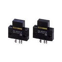
Photomicrosensors CONV REFL LIGHT-ON
Manufacturer
Omron
Series
-r
Specifications of EE-SPY412
Output Configuration
Light-On
Sensing Distance
5 mm
Sensing Method
Reflective
No. Of Pins
4
Opto Case Style
Module
No. Of Channels
1
Operating Temperature Range
-10°C To +55°C
Operating Voltage Max
24VDC
Operating Voltage Min
5VDC
Output Current Max
80mA
Sensing Object
White Paper
Sensing Light
Infrared
Mounting Type
Solder
Current - Supply
15mA
Voltage - Supply
5 V ~ 24 V
Package / Case
Module, Connector
Features
Reduced External Light Interference
Input Current
15mA
Input Current Max
50mA
Rohs Compliant
Yes
Lead Free Status / RoHS Status
Lead free / RoHS Compliant
Lead Free Status / RoHS Status
Lead free / RoHS Compliant, Lead free / RoHS Compliant
Available stocks
Company
Part Number
Manufacturer
Quantity
Price
Company:

Part Number:
EE-SPY412
Manufacturer:
Omron Electronics
Quantity:
135


Precautions
Refer to General Precautions on page 23 to 28 for general precautions.
Do not use this product in sensing devices designed
to provide human safety.
Dimensions (Unit: mm)
72
EE-SPY311
EE-SPY411
EE-SPY312
EE-SPY412
Accessories (Order Separately)
Refer to Connectors on page 97 for details on connectors.
EE-SPY31/41
Warning
Light Convergent Reflective Photomicrosensor
22.8
6.2
0.2
16.8
22.8
Four,
R2.1
6.2
8
16.8
Four,
R2.1
8
1
5 2.5
26
19
20
20
19
14
2 3
1
5 2.5
26
19
20
20
19
14
2 3
(back) (10 x 5)
Sensing face
Indicator window
(red)
Four, R1
Four, R1.6
Sensing face
(10 × 5)
Indicator window
(red)
3.2
3.2
Four, R1
Four, R1.6
13.7
Make sure that this product is used within the rated ambient
environment conditions.
● Wiring
3.2
3.2
• Connection is made using a connector. Do not solder to the pins
• When extending the cable, use an extension cable with conductors
• To use a cable length longer than 2 m, attach a capacitor with a
(leads).
having a total cross-section area of 0.3 mm
must be 2 m maximum.
capacitance of approximately 10 µF to the wires as shown below.
The distance between the terminal and the capacitor must be within
2 m. (Use a capacitor with a dielectric strength that is at least twice
the Sensor's power supply voltage.)
13.7
7.6
0.3 0.7
7.6
0.3 0.7
8
0.2
18.7
Precautions for Correct Use
OUT
2 m max.
A capacitor of
10 µF min.
5 to 24 DCV
0 V
Terminal Arrangement
Terminal Arrangement
(1)
(2)
(3)
(1)
(2)
(3)
2
Extension cable
. The total cable length
OUT
OUT
+
−
+
−
GND (0 V)
GND (0 V)
OUTPUT
OUTPUT
Vcc
Vcc
Related parts for EE-SPY412
Image
Part Number
Description
Manufacturer
Datasheet
Request
R

Part Number:
Description:
Photomicrosensors 13mm P Modulated SLOT PMS L-On
Manufacturer:
Omron
Datasheet:

Part Number:
Description:
Photomicrosensors PMOD 5mmSD D-ON SS
Manufacturer:
Omron
Datasheet:
Part Number:
Description:
Photomicrosensors DIFFUSE PMS PMOD 5mm
Manufacturer:
Omron
Datasheet:

Part Number:
Description:
Photomicrosensors CONV REFL DARK-ON
Manufacturer:
Omron
Datasheet:
Part Number:
Description:
Photomicrosensors 5MM LIGHT-ON REFLECT
Manufacturer:
Omron
Datasheet:

Part Number:
Description:
Photomicrosensors REFL PHOTO IC
Manufacturer:
Omron
Datasheet:
Part Number:
Description:
Photomicrosensors CONV REFL LIGHT-ON
Manufacturer:
Omron
Datasheet:

Part Number:
Description:
Photomicrosensors REFL LIGHT-ON/DRK-ON
Manufacturer:
Omron
Datasheet:
Part Number:
Description:
Photomicrosensors REFL LIGHT-ON/DRK-ON
Manufacturer:
Omron
Datasheet:

Part Number:
Description:
Photomicrosensors REFL LIGHT-ON
Manufacturer:
Omron
Datasheet:


Part Number:
Description:
PHOTO MICROSENSOR
Manufacturer:
Omron
Datasheet:

Part Number:
Description:
PHOTO MICROSENSOR :
Manufacturer:
Omron
Datasheet:

Part Number:
Description:
PHOTO MICROSENSOR
Manufacturer:
Omron
Datasheet:

Part Number:
Description:
PHOTO MICROSENSOR
Manufacturer:
Omron
Datasheet: