Morph-IC-II FTDI, Morph-IC-II Datasheet - Page 7
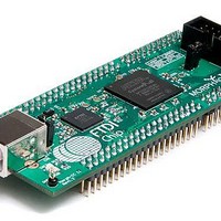
Morph-IC-II
Manufacturer Part Number
Morph-IC-II
Description
Interface Modules & Development Tools USB Hi-Speed Altera Cyclone-II FPGA Mod
Manufacturer
FTDI
Datasheet
1.MORPH-IC-II.pdf
(30 pages)
Specifications of Morph-IC-II
Interface Type
Programmable
Data Bus Width
Serial, 8 bit
Operating Supply Voltage
5 V
Product
Interface Modules
Features
Ultra Fast FPGA Configuration, JTAG Interface
Core Architecture
Cyclone
Core Sub-architecture
Cyclone II
Kit Contents
Board
Kit Features
FT2232HQ Dual, Hi-Speed USB UART/FIFO IC Used For USB
For Use With/related Products
FT2232H, EP2C5F256C8N
Lead Free Status / RoHS Status
Lead free / RoHS Compliant
Available stocks
Company
Part Number
Manufacturer
Quantity
Price


3.2 Getting Started
3.2.1 Configuring the Jumper settings
Morph-IC-II module has two jumpers labelled VBUS and V_BANK4.
A summary of the jumper functions is given in Table 1.
NOTE: When using V_BANK4, care must be taken regarding this jumper; if there is a large enough
discrepancy between the voltage that powers an IO Bank and the logic high voltage of the signals
processed by the bank damage can occur.
3.2.2 Configuring the FPGA
The Morph-IC-II package includes a *.RBF loader programme called “MorphLd”. This programme is used
to load RBF files into the FPGA of Morph-IC-II via the USB to Passive Serial interface. These *.RBF are
synthesised HDL (VHDL or Verilog) code with additional settings for the FPGA specified by the Quartus-II
options. These files are generated when a HDL project is compiled using (suitably configured) Quartus-II
or a similar HDL compiler. Using this utility along with Quartus-II the HDL code of an application can be
compiled and exported to Morph-IC-II.
(See AN_141_MorphIO-II and MorphLd Utilities for Morph-IC-II)
1) Jumper VBUS connects USB connector pin 1 to J1-1.
2) Jumper V_BANK4 connects 3V3IO to the power supply pins of Bank 4.
A) When jumper VBUS is closed, the Morph-IC-II module is powered from the USB bus. This
B) When jumper VBUS is open, the Morph-IC-II module requires an external voltage supply of 5
A) When jumper V_BANK4 is closed, a short is formed between 3V3IO and V_BANK4. This
B) When jumper V_BANK4 is open, an external voltage supply must be applied to J2-29 and J2-
connects the VBUS power from the USB host PC to the voltage regulator input of Morph-IC-II.
This voltage regulator provides power to the following: VCC3V3, VPLL and VUSB all of which
power the FT2232H chip. This mode is known as “bus powered mode”.
Volts DC applied to J1-1. This mode is known as “self powered mode”.
connection provides 3.3 volts to I/O Bank 4 of the FPGA.
NOTE: When this jumper is closed J2-29 and J2-30 must be unconnected or
connected to a 3V3 supply (this is the case for typical MorphIC-1K application
boards).
30 to power the I/O Bank 4. The voltage level supplied should match the voltage level of the
input signals.
Jumper Name
V_BANK4
V_BANK4
VBUS
VBUS
Copyright © 2010 Future Technology Devices International Limited
`
CLOSED
CLOSED
State
OPEN
OPEN
Table 1 – Jumper Description
3.3V needs to be applied to I/O Bank 4 via J2-29
An external voltage of either 1.5V, 1.8V, 2.5V or
An external supply needs to be applied via J1-1
3.3V supplied to I/O Bank 4
Powered from the USB Bus
and J2-30
Description
Document Reference No.: FT_000198
Clearance No.: FTDI#
MORPH-IC-II Datasheet
Version 1.03
6
164
Related parts for Morph-IC-II
Image
Part Number
Description
Manufacturer
Datasheet
Request
R

Part Number:
Description:
Interface Modules & Development Tools Obsolete See MORPH-IC-II
Manufacturer:
FTDI
Datasheet:

Part Number:
Description:
MODULE USB TO FPGA
Manufacturer:
FTDI, Future Technology Devices International Ltd
Datasheet:

Part Number:
Description:
BOARD, EVALUATION, UK PSU
Manufacturer:
FTDI
Datasheet:
Part Number:
Description:
BOARD, EVALUATION, US PSU
Manufacturer:
FTDI
Datasheet:
Part Number:
Description:
Specifications: Manufacturer: FTDI ; Product Category: USB Interface IC ; RoHS: Details ; Operating Supply Voltage: 3 V to 5.25 V ; Supply Current: 25 mA ; Maximum Operating Temperature: + 70 C ; Mounting Style: SMD/SMT ; Package / Case: QFN-32
Manufacturer:
FTDI
Part Number:
Description:
integr. usb2.0/uart lqfp32 rohs ftdi reel c1k...
Manufacturer:
FTDI
Datasheet:
Part Number:
Description:
Interface Development Tools USB to UART Breakout Board
Manufacturer:
FTDI
Datasheet:

Part Number:
Description:
IC USB TO SERIAL UART 32-QFN
Manufacturer:
FTDI, Future Technology Devices International Ltd

Part Number:
Description:
USB Interface IC USB to Serial UART Enhanced IC SSOP-28
Manufacturer:
FTDI
Datasheet:

Part Number:
Description:
IC, USB UART INTERFACE, SSOP-28
Manufacturer:
FTDI
Datasheet:

Part Number:
Description:
IC, USB UART INTERFACE, QFN-32
Manufacturer:
FTDI
Datasheet:
Part Number:
Description:
IC, USB FIFO INTERFACE, SSOP-28
Manufacturer:
FTDI
Datasheet:
Part Number:
Description:
MODULE, USB, 4 PORT, FT4232H BASED
Manufacturer:
FTDI
Datasheet:
Part Number:
Description:
357-036-542-201 CARDEDGE 36POS DL .156 BLK LOPRO
Manufacturer:
FTDI
Datasheet:
Part Number:
Description:
357-036-542-201 CARDEDGE 36POS DL .156 BLK LOPRO
Manufacturer:
FTDI
Datasheet: