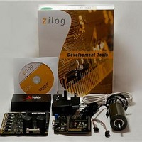
Z16FMC28200KITG Zilog, Z16FMC28200KITG Datasheet - Page 13

Z16FMC28200KITG
Manufacturer Part Number
Z16FMC28200KITG
Description
Power Management Modules & Development Tools Z16Motor Control Development Kit
Manufacturer
Zilog
Type
Motor / Motion Controllers & Driversr
Datasheet
1.Z16FMC28200KITG.pdf
(15 pages)
Specifications of Z16FMC28200KITG
Interface Type
RS-232
Operating Supply Voltage
5 V
Product
Power Management Development Tools
For Use With/related Products
Z16FMC
Lead Free Status / RoHS Status
Lead free / RoHS Compliant
Lead Free Status / RoHS Status
Lead free / RoHS Compliant
13. Slowly increase the adjustable 24 V DC power source from 0 V DC to 24 V DC. The 3-
14. Use the Direction switch S2 to change the direction in which the motor spins. Use
For more information about this demonstration software, refer to the Zilog Application
Note titled Sensorless BLDC Motor Control Using the ZNEO Z16FMC MCU (AN0311).
For more information about using Zilog Developer Studio II and building projects with
your Z16FMC Series Motor Control Development Kit, refer to the Zilog Developer Studio
II–ZNEO User Manual (UM0171).
Troubleshooting Tips
If you experience trouble running the sample code with the Z16FMC Series Motor Control
Development Kit, check the following before contacting Zilog Technical Support for
assistance:
•
•
•
•
•
•
•
QS007901-1110
phase motor should start running. If the motor does not run, start over from
page 9.
SPEED potentiometer R7 to adjust the motor RPM.
Verify that you are using ZDS II version 4.12.0 or later.
Ensure that you are using the unmodified sample project code as described in
ing the Sample Code
Verify that you have properly connected the opto-isolated USB Smart Cable to the
host PC and the MC MDS board as described in
Smart Cable
connector pin 1 of the MC MDS board.
After you have connected the 5 V DC power supply to the MC MDS board, green
3.3 V DC LED D1 must be on. If it is not illuminated, verify that power is properly
connected to the board as described in
Supply
In ZDS II, navigate to Project
serial number for the USB Optoisolator Smart Cable interface is present and selected.
If the serial number is missing, reinstall the opto-isolated USB Smart Cable driver
software.
In ZDS II, verify that Z16FMC28200KITG is selected as the target.
In ZDS II, navigate to Project
Tool selection is USB Smart Cable.
on page 5.
on page 7. Ensure that pin 1 of the cable is properly aligned with DBG
on page 6.
→
→
Settings
Settings
Z16FMC Series Motor Control Development Kit
Step 4. Connect the 5 V DC Universal Power
→
→
Debugger
Debugger and verify that your Debug
Step 3. Install the Opto-Isolated USB
→
Setup and verify that the
Quick Start Guide
Page 13 of 15
Step 3
Execut-
on


