CS-E9302 Olimex Ltd., CS-E9302 Datasheet - Page 7
CS-E9302
Manufacturer Part Number
CS-E9302
Description
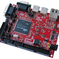
MCU, MPU & DSP Development Tools DEV BRD FOR EP9301/ EP9302 ARM920T
Manufacturer
Olimex Ltd.
Datasheet
1.CS-E9302.pdf
(20 pages)
Specifications of CS-E9302
Processor To Be Evaluated
EP9302 ARM920T
Interface Type
RS-232, Ethernet, USB, I2S, JTAG, SPI, UART
Dimensions
110 mm x 90 mm
Operating Supply Voltage
5 V
Silicon Manufacturer
Cirrus
Core Architecture
ARM
Core Sub-architecture
ARM9
Silicon Core Number
EP9
Kit Contents
Board
Rohs Compliant
Yes
Lead Free Status / RoHS Status
Lead free / RoHS Compliant
Other names
1776317 52R3485


RESET CIRCUIT:
CLOCK CIRCUIT:
JUMPER DESCRIPTION:
The EP9302 chip can be reset through the PRSTN pin(power on reset) or
through the open drain common reset pin(user reset) - RSTON pin.
PRSTN is a Power-on Reset realized with MCP130T Reset circuit with typical
2.9V threshold. On the board is present a PRN button which is used for
manual Power-on Reset.
The user reset – RSTON is common for the CS9203 microcontroller, PHY
chip, NOR flash, JTAG and MCP130 Supervisory circuit.
generated from JTAG pin(15), RSTN button, CS9302 or MCP130T Reset
circuit.
EP9302 generates its internal clock with PLL and uses single14.7456 MHz
crystal connected to EP9302 pin 119 (XTAL0) and pin 118 (XTAL1).
The Real Time Clock operates from a 32.768 KHz crystal.
Boot configuration jumpers:
The Hardware Configuration controls are defined by a set of device pins that
are latched into configuration control bits on the assertion of chip reset on
the rising edge of the PRSTN or RSTON pin. The different hardware
configuration bits define watchdog behavior, boot mode (internal or
external), boot synchronicity, and external boot width. The latched pins are:
EECLK
EEDAT
TEST[1:0]
–
The corresponding jumper is EECLK_L. When the
jumper is closed EECLK pin is log. “0”, otherwise – log.”1”.
–
The corresponding jumper is EEDAT_L. When the
jumper is closed EEDAT pin is log. “0”, otherwise – log.”1”.
–
The corresponding jumpers are T0_H/T0_L and T1_H/T1_L
When the T0_H/T0_L jumper is closed to T0_H side TEST0
pin is “1”. When the T0_H/T0_L jumper is closed to T0_L
side TEST0 pin is “0”.
When the T1_H/T1_L jumper is closed to T1_H side TEST1
pin is “1”. When the T1_H/T1_L jumper is closed to T1_L
side TEST1 pin is “0”.
Select internal or external boot
Should be pulled up to “1”
Select boot mode
It can be
Related parts for CS-E9302
Image
Part Number
Description
Manufacturer
Datasheet
Request
R

Part Number:
Description:
MCU, MPU & DSP Development Tools ETHERNET CONTROLLER HEADER BRD 50x40mm
Manufacturer:
Olimex Ltd.
Datasheet:

Part Number:
Description:
MCU, MPU & DSP Development Tools DEV PROTOTYPE BRD FOR TMS470A256
Manufacturer:
Olimex Ltd.
Datasheet:

Part Number:
Description:
MCU, MPU & DSP Development Tools ETHERNET CONTROLLER HEADER BRD 53x29mm
Manufacturer:
Olimex Ltd.
Datasheet:

Part Number:
Description:
MCU, MPU & DSP Development Tools MP3 PLYR MOD WVS1002 W/VS1002
Manufacturer:
Olimex Ltd.
Datasheet:

Part Number:
Description:
MCU, MPU & DSP Development Tools PoE INJECTOR FOR PIC-MICRO-WEB
Manufacturer:
Olimex Ltd.

Part Number:
Description:
Development Boards & Kits - ARM OLINUXINO MICRO SBC ALLWINNER A10S CTXA8
Manufacturer:
Olimex Ltd.
Part Number:
Description:
Other Development Tools EKG / EMG SHIELD FOR DUINOMITE
Manufacturer:
Olimex Ltd.

Part Number:
Description:
MCU, MPU & DSP Development Tools DEV BRD FOR LPC2378 512KB FLASH 16KB RAM
Manufacturer:
Olimex Ltd.

Part Number:
Description:
MCU, MPU & DSP Development Tools HDR BRD FOR LPC2294 1MB SRAM 4MB FLASH
Manufacturer:
Olimex Ltd.

Part Number:
Description:
MCU, MPU & DSP Development Tools DEV BRD FOR LPC2919 768KB FLASH 56KBSRAM
Manufacturer:
Olimex Ltd.
Datasheet:

Part Number:
Description:
Microcontroller & Microprocessor Development Tools TCP-IP DEV BRD PIC32MX460F512
Manufacturer:
Olimex Ltd.
Datasheet:

Part Number:
Description:
Microcontroller & Microprocessor Development Tools PROTOTYPE BOARD TMS320F28027
Manufacturer:
Olimex Ltd.
Datasheet:

Part Number:
Description:
Microcontroller & Microprocessor Development Tools HDR BRD FOR LPC3131
Manufacturer:
Olimex Ltd.
Datasheet:

Part Number:
Description:
Microcontroller & Microprocessor Development Tools MP3 PLYR MOD WITH VS1002
Manufacturer:
Olimex Ltd.
Datasheet:
Part Number:
Description:
Microcontroller & Microprocessor Development Tools MP3 PLYR MOD BAT WITH VS1002
Manufacturer:
Olimex Ltd.
Datasheet: