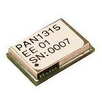
ENW-89818C2JF Panasonic, ENW-89818C2JF Datasheet - Page 16

ENW-89818C2JF
Manufacturer Part Number
ENW-89818C2JF
Description
Bluetooth / 802.15.1 Modules & Development Tools CC2560 HCI module no antenna
Manufacturer
Panasonic
Datasheet
1.ENW-89818C2JF.pdf
(41 pages)
Specifications of ENW-89818C2JF
Interface Type
I2C, SPI, UART
Data Rate
4 Mbps
Operating Voltage
3.3 V
Board Size
6.5 mm x 9 mm
Operating Temperature Range
- 20 C to + 70 C
Output Power
10.5 dBm
Technology/ Type
HCI Module
Processor Series
CC2560
For Use With/related Products
EVAL-PAN1315
Lead Free Status / RoHS Status
Lead free / RoHS Compliant
CLASSIFICATION
SUBJECT
CUSTOMER’S CODE
PAN1315
PANASONIC ELECTRONIC DEVICES EUROPE GMBH
11.1. PCM HARDWARE INTERFACE
11.2. DATA FORMAT
11.3. FRAME IDLE PERIOD
• Enlarged interface options to support a wider variety of codecs
• PCM bus sharing
The PCM interface is one implementation of the codec interface. It contains the
following four lines:
• Clock—configurable direction (input or output)
• Frame Sync—configurable direction (input or output)
• Data In—Input
• Data Out—Output/3-state
The Bluetooth device can be either the master of the interface where it generates the
clock and the frame-sync signals, or slave where it receives these two signals. The
PCM interface is fully configured by a vendor specific command.
For slave mode, clock input frequencies of up to 16 MHz are supported. At clock rates
above 12 MHz, the maximum data burst size is 32 bits. For master mode, the CC2560
can generate any clock frequency between 64 kHz and 6 MHz.
The data format is fully configurable:
• The data length can be from 8 to 320 bits, in 1-bit increments, when working with two
channels, or up to 640 bits when using 1 channel. The Data length can be set
independently for each channel.
• The data position within a frame is also configurable in with 1 clock (bit) resolution and
can be set independently (relative to the edge of the Frame Sync signal) for each
channel.
• The Data_In and Data_Out bit order can be configured independently. For example;
Data_In can start with the MSB while Data_Out starts with LSB. Each channel is
separately configurable. The inverse bit order (that is, LSB first) is supported only for
sample sizes up to 24 bits.
• It is not necessary for the data in and data out size to be the same length.
• The Data_Out line is configured to ‘high-Z’ output between data words. Data_Out can
also be set for permanent high-Z, irrespective of data out. This allows the CC2560 to be
a bus slave in a multi-slave PCM environment. At powerup, Data Out is configured as
high-Z.
The codec interface has the capability for frame idle periods, where the PCM clock can
“take a break” and become ‘0’ at the end of the PCM frame, after all data has been
transferred.
The CC2560 supports frame idle periods both as master and slave of the PCM bus.
When CC2560 is the master of the interface, the frame idle period is configurable. There
are two configurable parameters:
• Clk_Idle_Start – Indicates the number of PCM clock cycles from the beginning of the
frame until the beginning of the idle period. After Clk_Idle_Start clock cycles, the clock
will become ‘0’.
CLASS 1 or 2 BLUETOOTH MODULE
PRODUCT SPECIFICATION
PANASONIC’S CODE
ENW89818C2JF
No.
DS-1315-2400-102
PAGE
DATE
www.pedeu.pansonic.de
23.05.2011
16 of 41
REV.
1.03


