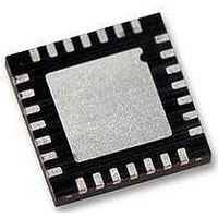
WM8986GECO/V Wolfson Microelectronics, WM8986GECO/V Datasheet - Page 61

WM8986GECO/V
Manufacturer Part Number
WM8986GECO/V
Description
Audio Amplifiers Class D Headphone DAC + Line Out
Manufacturer
Wolfson Microelectronics
Datasheet
1.WM8986GECOV.pdf
(88 pages)
Specifications of WM8986GECO/V
Product
Class-D
Output Power
40 mW
Thd Plus Noise
- 86 dB
Operating Supply Voltage
1.71 V to 3.6 V, 2.5 V to 3.6 V
Maximum Operating Temperature
+ 85 C
Mounting Style
SMD/SMT
Audio Load Resistance
16 Ohms
Minimum Operating Temperature
- 40 C
Output Signal Type
Differential
Supply Voltage (max)
3.6 V
Supply Voltage (min)
1.71 V, 2.5 V
Output Type
Differential
Package / Case
QFN-28
Lead Free Status / RoHS Status
Lead free / RoHS Compliant
Production Data
OUTPUT SWITCHING (JACK DETECT)
w
For further details of the jack detect operation see the OUTPUT SWITCHING section.
When the device is operated using a 2-wire interface the CSB/GPIO1 pin can be used as a switch
control input to automatically disable one set of outputs and enable another; the most common use
for this functionality is as jack detect circuitry.
The GPIO pins have an internal de-bounce circuit when in this mode in order to prevent the output
enables from toggling multiple times due to input glitches. This de-bounce circuit is clocked from a
slow clock with period 2
Notes:
The SLOWCLKEN bit must be enabled for the jack detect circuitry to operate.
The GPIOPOL bit is not relevant for jack detection, it is the signal detected at the pin which is used
Switching on/off of the outputs is fully configurable by the user. Each output, OUT1, OUT2, OUT3
and OUT4 has 2 associated enables. OUT1_EN_0, OUT2_EN_0, OUT3_EN_0 and OUT4_EN_0 are
the output enable signals which are used if the selected jack detection pin is at logic 0 (after de-
bounce). OUT1_EN_1, OUT2_EN_1, OUT3_EN_1 and OUT4_EN_1 are the output enable signals
which are used if the selected jack detection pin is at logic 1 (after de-bounce).
The jack detection enables operate as follows:
All OUT_EN signals have an AND function performed with their normal enable signals (in Table 28).
When an output is normally enabled at per Table 28, the selected jack detection enable (controlled
by selected jack detection pin polarity) is set 0; it will turn the output off. If the normal enable signal is
already OFF (0), the jack detection signal will have no effect due to the AND function.
During jack detection if the user desires an output to be un-changed whether the jack is in or not,
both the JD_EN settings, i.e. JD_EN0 and JD_EN1, should be set to 0000.
If jack detection is not enabled (JD_EN=0), the output enables default to all 1’s, allowing the outputs
to be controlled as normal via the normal output enables found in Table 28.
21
x MCLK and is enabled by the SLOWCLKEN bit.
PD, Rev 4.1, June 2009
WM8986
61


