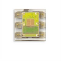
TSL27711FN TAOS, TSL27711FN Datasheet - Page 2

TSL27711FN
Manufacturer Part Number
TSL27711FN
Description
Light to Digital Converters Light to Digital w/Proximity
Manufacturer
TAOS
Datasheet
1.TSL27713FN.pdf
(36 pages)
Specifications of TSL27711FN
Data Bus Width
16 bit
Peak Wavelength
640 nm, 850 nm
Maximum Operating Frequency
795 KHz
Operating Supply Voltage
2.4 V to 3.6 V
Operating Current
175 uA
Maximum Operating Temperature
+ 70 C
Minimum Operating Temperature
- 30 C
Interface Type
I2C
Maximum Fall Time
300 ns
Maximum Rise Time
300 ns
Mounting Style
SMD/SMT
Resolution
16 bit
Package / Case
DFN-6
Lead Free Status / RoHS Status
Lead free / RoHS Compliant
Available stocks
Company
Part Number
Manufacturer
Quantity
Price
Company:
Part Number:
TSL27711FN
Manufacturer:
TI
Quantity:
1 893
TSL2771
LIGHT-TO-DIGITAL CONVERTER
with PROXIMITY SENSING
TAOS100A − FEBRUARY 2010
Functional Block Diagram
Detailed Description
2
Copyright E 2010, TAOS Inc.
The TSL2771 light-to-digital device provides on-chip clear and IR diodes, integrating amplifiers, ADCs,
accumulators, clocks, buffers, comparators, a state machine and an I
clear photodiode (visible plus infrared) and one infrared-responding (IR) photodiode. Two integrating ADCs
simultaneously convert the amplified photodiode currents into a digital value providing up to 16 bits of resolution.
Upon completion of the conversion cycle, the conversion result is transferred to the clear and IR data registers.
This digital output can be read by a microprocessor through which the illuminance (ambient light level) in Lux
is derived using an empirical formula to approximate the human eye response.
Communication to the device is accomplished through a fast (up to 400 kHz), two-wire I
connection to a microcontroller or embedded controller. The digital output of the TSL2771 device is inherently
more immune to noise when compared to an analog interface.
The TSL2771 provides a separate pin for level-style interrupts. When interrupts are enabled and a pre-set value
is exceeded, the interrupt pin is asserted and remains asserted until cleared by the controlling firmware. The
interrupt feature simplifies and improves system efficiency by eliminating the need to poll a sensor for a light
intensity or proximity value. An interrupt is generated when the value of an ALS or proximity conversion exceeds
either an upper or lower threshold. In addition, a programmable interrupt persistence feature allows the user
to determine how many consecutive exceeded thresholds are necessary to trigger an interrupt. Interrupt
thresholds and persistence settings are configured independently for both ALS and proximity.
Proximity detection requires only a single external IR LED. An internal LED driver can be configured to provide
a constant current sink of 12.5 mA, 25 mA, 50 mA, or 100 mA of current. No external current limiting resistor
is required. The number of proximity LED pulses can be programmed from 1 to 255 pulses. Each pulse has a
16-μs period. This LED current coupled with the programmable number of pulses provides a 2000:1 contiguous
dynamic range.
V
DD
to 3.6 V
= 2.4 V
GND
LDR
Integration
Clear
Prox
IR
r
IR LED Constant
Clear
Prox
ADC
ADC
ADC
Current Sink
Prox Control
Wait Control
ALS Control
IR
www.taosinc.com
Clear
Data
Prox
Data
Data
IR
Lower Limit
Lower Limit
Upper Limit
Upper Limit
Interrupt
2
C interface. Each device combines one
r
The LUMENOLOGY r Company
SCL
SDA
2
INT
C serial bus for easy


