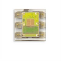
TSL27711FN TAOS, TSL27711FN Datasheet - Page 5

TSL27711FN
Manufacturer Part Number
TSL27711FN
Description
Light to Digital Converters Light to Digital w/Proximity
Manufacturer
TAOS
Datasheet
1.TSL27713FN.pdf
(36 pages)
Specifications of TSL27711FN
Data Bus Width
16 bit
Peak Wavelength
640 nm, 850 nm
Maximum Operating Frequency
795 KHz
Operating Supply Voltage
2.4 V to 3.6 V
Operating Current
175 uA
Maximum Operating Temperature
+ 70 C
Minimum Operating Temperature
- 30 C
Interface Type
I2C
Maximum Fall Time
300 ns
Maximum Rise Time
300 ns
Mounting Style
SMD/SMT
Resolution
16 bit
Package / Case
DFN-6
Lead Free Status / RoHS Status
Lead free / RoHS Compliant
Available stocks
Company
Part Number
Manufacturer
Quantity
Price
Company:
Part Number:
TSL27711FN
Manufacturer:
TI
Quantity:
1 893
Proximity Characteristics, V
§
Wait Characteristics, V
AC Electrical Characteristics, V
†
The LUMENOLOGY r Company
I
f
t
t
t
t
t
t
t
t
t
t
C
DD
Proximity Distance is dependent upon emitter properties the reflective properties of the proximity reflecting surface. The nominal value shown
uses an IR emitter with a peak wavelength of 850nm and a 20° half angle. The proximity reflecting surface used is a 16” x 20” Kodak 90% grey
card. 60 mw/SR, 100 mA, 64 pulses, open view (no glass). Note: Greater distances are achievable with appropriate system considerations.
(SCL)
(BUF)
(HDSTA)
(SUSTA)
(SUSTO)
(HDDAT)
(SUDAT)
(LOW)
(HIGH)
F
R
Specified by design and characterization; not production tested.
i
Supply current — LDR pulse on
ADC conversion time step size
ALS ADC number of integration steps
Full scale ADC counts per step
Proximity IR LED pulse count
Proximity pulse period
Proximity pulse — LED on time
Proximity LED Drive
Proximity LED Drive
Proximity distance §
Wait step size
Wait number of integration steps
Clock frequency (I
Bus free time between start and stop condition
Hold time after (repeated) start condition. After
this period, the first clock is generated.
Repeated start condition setup time
Stop condition setup time
Data hold time
Data setup time
SCL clock low period
SCL clock high period
Clock/data fall time
Clock/data rise time
Input pin capacitance
PARAMETER
PARAMETER
PARAMETER
2
DD
C only)
= 3 V, T
†
DD
= 3 V, T
DD
A
PTIME = 0xFF
Two or more pulses
I
I
LDR pin
WTIME = 0xFF
SINK
SINK
= 3 V, T
r
= 255C, Gain = 16, WEN = 1 (unless otherwise noted)
sink current @ 600 mV,
sink current @ 600 mV,
A
TEST CONDITIONS
TEST CONDITIONS
www.taosinc.com
= 255C, Gain = 16, PEN = 1 (unless otherwise noted)
A
= 255C (unless otherwise noted)
TEST CONDITIONS
CONDITION
PDRIVE=0
PDRIVE=1
PDRIVE=2
PDRIVE=3
CHANNEL
LIGHT-TO-DIGITAL CONVERTER
r
with PROXIMITY SENSING
2.58
2.58
MIN
MIN
MIN
100
75
1.3
0.6
0.6
0.6
1.3
0.6
1
0
1
0
0
TAOS100A − FEBRUARY 2010
1024
TYP
2.72
7.33
12.5
TYP
2.72
Copyright E 2010, TAOS Inc.
100
TYP
16
50
25
18
3
MAX
MAX
MAX
400
300
300
256
255
125
256
10
2.9
2.9
TSL2771
UNIT
pulses
inches
kHz
steps
steps
steps
UNIT
UNIT
μs
μs
μs
μs
μs
μs
μs
pF
ns
ns
ns
mA
mA
mA
ms
ms
μs
μs
5


