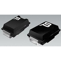
TISP4350T3BJR-S Bourns Inc., TISP4350T3BJR-S Datasheet - Page 2

TISP4350T3BJR-S
Manufacturer Part Number
TISP4350T3BJR-S
Description
Sidacs 275V(DRM)250A(IPP)350V(BO)
Manufacturer
Bourns Inc.
Datasheet
1.TISP4350T3BJR-S.pdf
(6 pages)
Specifications of TISP4350T3BJR-S
Breakover Voltage Vbo
+/- 350 V
Breakover Current Ibo Max
30 A
Rated Repetitive Off-state Voltage Vdrm
275 V
Off-state Leakage Current @ Vdrm Idrm
0.005 mA
Forward Voltage Drop
3 V
Off-state Capacitance Co
16 pF, 20 pF, 43 pF, 48 pF, 54 pF
Maximum Operating Temperature
+ 150 C
Mounting Style
SMD/SMT
Package / Case
DO-214AA
Minimum Operating Temperature
- 40 C
Breakover Voltage Range
± 350V
Breakover Current Max.
800A
Thyristor Case
SMB
No. Of Pins
2
Rohs Compliant
Yes
Svhc
No SVHC (20-Jun-2011)
Lead Free Status / RoHS Status
Lead free / RoHS Compliant
Available stocks
Company
Part Number
Manufacturer
Quantity
Price
Company:
Part Number:
TISP4350T3BJR-S
Manufacturer:
BOURNS
Quantity:
10 536
After a TIA/EIA-IS-968 Type B surge the equipment must be operational. As the TISP4350T3BJ has a current rating of 120 A, it will survive both
Type B surges, metallic (25 A, 9/720) and longitudinal (37.5 A, 9/720), giving an operational pass to FCC Part 68 Type B surges.
The TIA/EIA-IS-968 B type ringer has voltages of 56.5 V d.c. and up to 150 V rms a.c., giving a peak voltage of 269 V. The TISP4350T3BJ will
not clip the B type ringing voltage as it has a high impedance up to 275 V.
Repetitive peak off-state voltage (see Note 1)
Non-repetitive peak on-state pulse current (see Notes 1 and 2)
Non-repetitive peak on-state current (see Notes 1, 2 and 3)
Initial rate of rise of on-s tate current, Linear current ramp, Maximum ramp value < 50 A
Junction temperature
Storage temperature range
NOTES: 1. Initially, the device must be in thermal equilibrium with T
Description (Continued)
Absolute Maximum Ratings, T A = 25
Overload Ratings, T A = 25
Peak overload on-state current, a.c. power line cross tests UL 60950 (see Note 4)
NOTE
TISP4xxxT3BJ Overvoltage Protector Series
2/10 (Telcordia GR-1089-CORE, 2/10 voltage wave shape)
8/20 (IEC 61000-4-5, combination wave generator, 1.2/50 volt age wave shape)
10/160 (TIA/EIA-IS-968 (replaces FCC Part 68), 10/160 voltage wave shape)
5/310 (ITU-T K.44, 10/700 voltage wave shape used in K.20/45/21)
5/320 (TIA/EIA-IS-968 (replaces FCC Part 68), 9/720 voltage wave shape)
10/560 (TIA/EIA-IS-968 (replaces FCC Part 68), 10/560 voltage wave shape)
10/1000 (Telcordia GR-1089-CORE, 10/1000 voltage wave shape)
20 ms (50 Hz), full sine wave
16.7 ms (60 Hz), full sine wave
1000 s 50 Hz/60 Hz
2. These non-repetitive rated currents are peak values of either polarity. The surge may be repeated after the device returns to its
3. EIA/JESD51-2 environment and EIA/JESD51-3 PCB with standard footprint dimensions connected with 5 A rated printed wiring
4: These electrical stress levels may damage the device silicon chip. After test, the pass criterion is either that the device is
initial conditions.
track widths. Derate current values at -0.61 %/°C for ambient temperatures above 25 °C.
functional or, if it is faulty, that it has a short circuit fault mode. In the short circuit fault mode, the following equipment is protected
as the device is a permanent short across the line. The equipment would be unprotected if an open circuit fault mode developed.
°
C (Unless Otherwise Noted)
°
C (Unless Otherwise Noted)
Rating
Rating
J
= 25 °C.
Customers should verify actual device performance in their specific applications.
’4290T3
’4350T3
’4400T3
Symbol
Symbol
Specifications are subject to change without notice.
di
I
V
I
PPSM
I
T(OV)M
T
TSM
DRM
T
T
stg
/dt
J
DECEMBER 2001 - REVISED MAY 2008
-40 to +150
-65 to +150
See Figure 4
versus time
for current
Value
Value
±250
±220
±275
±335
±150
±120
±120
±100
±250
500
±80
2.1
25
30
Unit
A/µs
Unit
A rms
°C
°C
A
A
V


