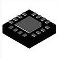
MAX5974AETE+ Maxim Integrated Products, MAX5974AETE+ Datasheet - Page 22

MAX5974AETE+
Manufacturer Part Number
MAX5974AETE+
Description
Current Mode PWM Controllers ACTIVE-CLAMPED CUR MODE PWM CONTLR
Manufacturer
Maxim Integrated Products
Datasheet
1.MAX5974DETE.pdf
(26 pages)
Specifications of MAX5974AETE+
Duty Cycle (max)
82 %
Mounting Style
SMD/SMT
Switching Frequency
600 KHz
Operating Supply Voltage
12 V to 21 V
Supply Current
1.8 mA
Maximum Operating Temperature
+ 85 C
Fall Time
14 ns
Minimum Operating Temperature
- 40 C
Rise Time
27 ns
Package / Case
TQFN-16
Lead Free Status / RoHS Status
Lead free / RoHS Compliant
During on-time, the coupled output is:
where V
Care must be taken to ensure that the voltage at FB
(equal to V
resistive divider) is not more than 5V:
If this condition is not met, a signal diode should be
placed from GND (anode) to FB (cathode).
Active-Clamped, Spread-Spectrum,
Current-Mode PWM Controllers
22
V
FB-ON
S
V
COUPLED-ON
is the input supply voltage.
COUPLED-ON
=
V
COUPLED-ON
= −
attenuated by the feedback
(V
S
×
×
(
N
N
R
S
P
FB1
−
R
V
FB2
+
OUT
R
FB2
)
N
N
)
C
O
<
5V
Typically, there are two sources of noise emission in a
switching power supply: high di/dt loops and high dV/dt
surfaces. For example, traces that carry the drain current
often form high di/dt loops. Similarly, the heatsink of the
main MOSFET presents a dV/dt source; therefore, mini-
mize the surface area of the MOSFET heatsink as much
as possible. Keep all PCB traces carrying switching cur-
rents as short as possible to minimize current loops. Use
a ground plane for best results.
For universal AC input design, follow all applicable
safety regulations. Offline power supplies can require
UL, VDE, and other similar agency approvals.
Layout Recommendations


