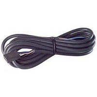
EE-1006 Omron, EE-1006 Datasheet

EE-1006
Specifications of EE-1006
Available stocks
Related parts for EE-1006
EE-1006 Summary of contents
Page 1
... Dark-ON when the L terminal of the connector is opened, and light-ON when the L terminal and positive (+) terminal are connected. Do not connect the L terminal when using dark-ON operation. When using light-ON useful to select the connector EE-1001-1. The L terminal and positive (+) terminal of this connector are connected in advance. ...
Page 2
... Model length EE-1001 EE-1001-1 L terminal and positive (+) terminal are already short-circuited. EE-1009 EE-1006 EE-1010 EE-1006 EE-1010 EE-1010-R EE-1010-R EE-1006A For EE-1006 only. Cable Model length EE-1016-R-1 For EE-SX67@-C1J-R only. EE-SX47/67 Infrared light Model method NPN output PNP output EE-SX670P-WR EE-SX670-WR 1M ...
Page 3
... Cover Polycarbonate al Emitter/receiver *1. The indicator is a GaP red LED (peak wavelength: 690 nm). *2. The response frequency was measured by detecting the rotating disk shown at the right. Connector for the EE-SX67 with Junction Connector Product Connector with Robot Cable Model EE-1016-R-1 Appearance Item Contact resistance 25 mΩ ...
Page 4
... Engineering Data (Typical) Sensing Position Characteristics Dark- OFF 0 1.0 2.0 3.0 4.0 5.0 6.0 Distance d (mm) I/O Circuit Diagrams NPN Output Output Model configuration Light indicator (red) Output Light-ON transistor Load 1 (e.g., relay) EE-SX67@ Load 2 EE-SX67@-WR EE-SX67@-CJ1-R Light indicator (red) ...
Page 5
... Check the dimensional diagrams. Light indicator (red) OUT Main IC circuit Load Precautions for Correct Use Permissible Remarks time The portion between the base of the 3 s max. terminals and the position 1.5 mm from the terminal base must not be soldered VDC VDC 5 ...
Page 6
... In the following diagrams, 376d EE-SX@70@ indicates the lot number and factory where the product was manufactured. Do not include this EE-SX670 code with the model number when ordering. Model number 376d Lot number and factory code EE-SX47/67 6 ...
Page 7
... Optical 9 axis 13.8 8.4 13.2 Two, 5.5 3.8 dia. holes 3.8 Indicator window 6 2.54 Tolerance class IT16 applies to dimensions in this datasheet unless otherwise specified. EE-SX671/671P EE-SX671A/671R Vcc EE-SX471/471P L L* OUT OUTPUT GND (0 V) 3.2 14.5 6.4 0.8 3.8 6 7.2 3 ...
Page 8
... EE-SX672/672P Terminal Arrangement EE-SX672A/672R EE-SX472/472P (1) (2) (3) (4) * Pin 2 is not used for the EE-SX472. 26 6.4 0 4.3 Four, R1.6 22.2 8.4 6.2 6.3 Four, R1 3.8 6.2 2.5 0.3 0.7 19 EE-SX673/673P EE-SX673A/673R EE-SX473/473P Vcc L L* OUT OUTPUT GND (0 V) 13.7 3 12.6 6.3 12.8 3 ...
Page 9
... EE-SX674/674P EE-SX674A/674R Terminal Arrangement EE-SX474/474P (1) (2) (3) (4) * Pin 2 is not used for the EE-SX474. Two, 3.5 dia. holes Two Indicator window 7 21.5 6. 3 (2.9) Optical axis 2 (9.3) 2.1 0.3 6.2 0.7 0.6 13.6 EE-SX676/676P Terminal Arrangement (1) (2) (3) (4) 13.7 Optical axis 2 ...
Page 10
... EE-SX671-C1J-R/671P-C1J-R Vcc (2) L (3) GND (0 V) (4) OUTPUT 9.4 2 R3.5 17 3.2 100 R1 ±15 Indicator window EE-SX670-C1J-R 6.35 0.8 2 Sensing window 9 15.5 3.6 EE-SX673-WR/673P-WR EE-SX673-C1J-R/673P-C1J-R Vcc (2) L (3) GND (0 V) (4) OUTPUT 13.7 7 12.6 6.3 12.8 3 13.4 5 Optical axis 9 14.4 Indicator 26.2 window 2.8 8.9 3 2.5 ...
Page 11
... Indicator window 2 Robot cable of 2.8 dia., 4 cores, 2 (0.15 mm with 0.8 mm dia. insulator); Standard length 4.6 dia. Accessories (Order Separately) Connector for the EE-SX67 with Junction Connector EE-SX675-WR/675P-WR EE-SX675-C1J-R/675P-C1J-R Terminal Arrangement Brown (1) Vcc Pink (2) L Blue (3) GND(0V) Black (4) OUTPUT 9 ...
Page 12
... EE-1016-R Refer to Accessories for details. 5 2,000 Robot cable of 2.8 dia., 4 cores, 2 (0.15 mm with 0.8 mm dia. insulator); Standard length EE-SX47/67 16 Terminal Arrangement (1) Brown (2) L Pink (3) Blue (4) OUT Black 12 ...
Page 13
... Please read and understand this catalog before purchasing the products. Please consult your OMRON representative if you have any questions or comments. WARRANTY OMRON's exclusive warranty is that the products are free from defects in materials and workmanship for a period of one year (or other period if specified) from date of sale by OMRON. OMRON MAKES NO WARRANTY OR REPRESENTATION, EXPRESS OR IMPLIED, REGARDING NON-INFRINGEMENT, MERCHANTABILITY, OR FITNESS FOR PARTICULAR PURPOSE OF THE PRODUCTS ...


