RF180-5 TELEDYNE, RF180-5 Datasheet

RF (Radio Frequency) Relays 5V DC-6GHz .15W

RF180-5

Manufacturer Part Number
RF180-5
Description
RF (Radio Frequency) Relays 5V DC-6GHz .15W
Manufacturer
TELEDYNE
Series
RF180r
Datasheets

Specifications of RF180-5

Coil Resistance
61 Ohms
Frequency
6 GHz
Contact Form
DPDT
Coil Voltage
5 VDC
Power Consumption
290 mW
Termination Style
PCB
Brand/series
RF180 Series
Capacitance
0.02 pF (Typ.)
Current, Rating
0.25 A
Diameter, Body
0.370 in. (Max.)
Diameter, Lead
0.017 in.
Function
Latching
Height
0.300 in. (Max.)
Latch Type
Magnetic
Length, Lead
0.75 in.
Mounting Type
PCB
Number Of Pins
10
Package Type
TO-5
Relay Type
Electro Mechanical
Resistance, Coil
61 Ohms +⁄- 20% @ 25 °C
Resistance, Contact
0.15 Ohm (Max.) (Before Life), 0.25 Ohm (Max.) (After Life)
Temperature, Operating
-55 to +85 °C
Termination
Leadwires
Voltage, Control
5 VDC
Voltage, Rating
28 VDC
Lead Free Status / RoHS Status
Lead free / RoHS Compliant
RF180 Page
DESCRIPTION
The Series RF180 relay is an ultraminiature, hermetically
sealed, magnetic-latching relay featuring extremely low
intercontact capacitance for exceptional RF performance
over the full UHF spectrum. Its low profile height and .100"
grid spaced terminals make it ideal for applications where
extreme packaging density and/or close PC board spacing
are required.
The RF180 design has been optimized for use in RF
attenuators, RF switch matrices, and other applications
requiring magnetic latching, high isolation, low insertion loss
and low VSWR.
Unique construction features and manufacturing techniques
provide high reliability and excellent robustness to
environmental extremes.
PRINCIPLE OF OPERATION
Energizing Coil A produces a
magnetic field opposing the
magnetic
permanent magnet in Circuit
A. As the net holding force
decreases,
force in the air gap of Circuit
B, which also results from the
magnetic
permanent magnet, becomes
great enough to break the
armature free of Core A, and
snap it into a closed position against Core B. The armature remains in this
position upon removal of power from Coil A, but will snap back into position
A upon energizing Coil B. Since operation depends upon cancellation of a
magnetic field, it is necessary to apply the correct polarity to the relay coils
as indicated on the relay schematic.
When latching relays are installed in equipment, the latch and reset coils
should not be pulsed simultaneously. Coils should not be pulsed with less
than rated coil voltage and the pulse width should be a minimum of three
times the specified operate time of the relay. If these conditions are not
followed, it is possible for the relay to be in the magnetic neutral position.
field
field
the
attractive
of
of
the
the
SPECIFICATIONS ARE SUBJECT TO CHANGE WITHOUT NOTICE
MAGNETIC CIRCUIT B
AIR GAP
COIL B
PERMANENT MAGNET
MAGNETIC-LATCHING,
ARMATURE
BROADBAND
www.teledynerelays.com
RF RELAYS
MAGNETIC CIRCUIT A
SOFT IRON CORE A
SOFT IRON FRAME
DPDT
COIL A
MOVING
CONTACT
• All welded construction.
• Unique uniframe design provides high magnetic efficiency
• High force/mass ratios for resistance to shock and vibration.
• Advanced
• Gold-plated precious metal alloy contacts ensure reliable
The RF180 relay is ideally suited for applications where
power dissipation must be minimized. The relays can be
operated with a short-duration coil voltage pulse. After the
contacts have transferred, no coil power is required.
The magnetic-latching feature of the RF180 provides a
nonvolatile memory capability, since the relays will not reset
upon removal of coil power.
and mechanical rigidity.
assurance of internal cleanliness.
d.c. switching from dry-circuit to 1/4 amp, as well as low
and stable insertion loss in RF applications.
STATIONARY
CONTACT
cleaning
Temperature
(Ambient)
Vibration
(General Note 1)
Shock
(General Note 1)
Enclosure
Weight
PHYSICAL SPECIFICATIONS
techniques
ENVIRONMENTAL AND
Storage
Operating –55°C to +85°C
©2003 TELEDYNE RELAYS
provide
RF180
SERIES
–65°C to +125°C
30 g’s to 3000 Hz
100 g’s,
6 msec, half-sine
Hermetically sealed
0.10 oz. (2.9g) max.
maximum
RF180/1203/Q1

Related parts for RF180-5

RF180-5 Summary of contents

Page 1

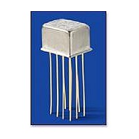
... PC board spacing are required. The RF180 design has been optimized for use in RF attenuators, RF switch matrices, and other applications requiring magnetic latching, high isolation, low insertion loss and low VSWR. ...

Page 2

... RF180 Time Response (RF Note 6) 90% 37ps reference 62ps propagation delay time 60ps pulse rise time 10% 0 100 200 300 400 500 600 Time (ps) ® 6002 with SMA connectors. (RT/duroid www.teledynerelays.com ...

Page 3

... Contact factory 290 milliwatts typical at nominal rated voltage @25°C 2.0 msec. maximum at nominal rated coil voltage 6.0 msec. width at rated voltage 0.02 pf typical 1,000 MΩ minimum between mutually isolated terminals Atmospheric pressure: 350 Vrms (60 Hz) RF180-5 Nom. 5.0 Max. 6.0 61 3.5 OUTLINE DIMENSIONS ...

Page 4

... J114, J114D, J114DD MAX ER134, ER134D, ER134DD, J134, J134D, J134DD RF100 RF103 122C, A152 ER116C, J116C H Dim MAX ER136C, J136C RF180 A150 SPECIFICATIONS SUBJECT TO CHANGE WITHOUT NOTICE Dim. H Max. .295 (7.49) .300 (7.62) .305 (7.75) .400 (10.16) .410 (10.41) .350 (8.89) .295 (7.49) ...

Page 5

... MAX .014 [0.36] (REF) .370 [9.4] MIN ♦ +44 (0) 1236 453124 • www.teledyne-europe.com For use with the following: ER411T, J411T, ER412, ER412D ER412DD, J412, J412D, J412DD ER412T, J412T 712, 712D, 712TN ER431T, J431T, ER432, ER432D ER432DD, J432, J432D, J432DD ER432T, J432T ...

Page 6

... RF320, RF323 .100 [2.54] .100 [2.54] .050 [1.27] .100 [2.54] Centigrid® Relays: RF180, ER116C, 122C, ER136C Indicates ground pin position Indicates glass insulated lead position Indicates ground pin or lead position depending on relay type © 2008 Teledyne Relays "Z" POSITION "X" POSITION " ...

Related keywords