RF180-5 TELEDYNE, RF180-5 Datasheet - Page 3
RF180-5
Manufacturer Part Number
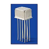
RF180-5
Description
RF (Radio Frequency) Relays 5V DC-6GHz .15W
Manufacturer
TELEDYNE
Series
RF180r
Specifications of RF180-5
Coil Resistance
61 Ohms
Frequency
6 GHz
Contact Form
DPDT
Coil Voltage
5 VDC
Power Consumption
290 mW
Termination Style
PCB
Brand/series
RF180 Series
Capacitance
0.02 pF (Typ.)
Current, Rating
0.25 A
Diameter, Body
0.370 in. (Max.)
Diameter, Lead
0.017 in.
Function
Latching
Height
0.300 in. (Max.)
Latch Type
Magnetic
Length, Lead
0.75 in.
Mounting Type
PCB
Number Of Pins
10
Package Type
TO-5
Relay Type
Electro Mechanical
Resistance, Coil
61 Ohms +⁄- 20% @ 25 °C
Resistance, Contact
0.15 Ohm (Max.) (Before Life), 0.25 Ohm (Max.) (After Life)
Temperature, Operating
-55 to +85 °C
Termination
Leadwires
Voltage, Control
5 VDC
Voltage, Rating
28 VDC
Lead Free Status / RoHS Status
Lead free / RoHS Compliant


RF180 Page
SERIES RF180
GENERAL ELECTRICAL SPECIFICATIONS (@ 25°C) (General Note 2)
DETAILED ELECTRICAL SPECIFICATIONS (@ 25°C) (General Note 2)
GENERAL NOTES
1. Relays will exhibit no contact chatter in
2. Unless otherwise specified, parameters
3. For extended contact life ratings, contact
4. Contacts shown in position resulting
excess of 10 µsec or transfer in excess
of 1 µsec.
are initial values.
factory.
when Coil B last energized.
Contact Arrangement
Rated Duty
Contact Resistance
Contact Load Rating (DC)
Characteristic Contact Life
Ratings (General Note 3)
Contact Overload Rating
Contact Carry Rating
Coil Operating Power
Operate Time
Minimum Operate Pulse
Interconnect Capacitance
Insulation Resistance
Dielectric Strength
Coil Voltage (Vdc)
Coil Resistance (Ohms ±20%)
Set & Reset Voltage (Vdc max.)
BASE PART NUMBERS
SPECIFICATIONS ARE SUBJECT TO CHANGE WITHOUT NOTICE
2 Form C (DPDT)
Continuous
0.15Ω maximum before life; 0.25Ω maximum after life at 0.25A/28Vdc (measured 1/8" from header)
Resistive:
Low Level:
10,000,000 cycles (typical) at low level (General Note 3)
100,000 cycles minimum at all other loads specified above
0.5A/28Vdc Resistive (100 cycles minimum)
Contact factory
290 milliwatts typical at nominal rated voltage @25°C
2.0 msec. maximum at nominal rated coil voltage
6.0 msec. width at rated voltage
0.02 pf typical
1,000 MΩ minimum between mutually isolated terminals
Atmospheric pressure: 350 Vrms (60 Hz)
Nom.
Max.
DIMENSIONS ARE SHOWN IN INCHES (MILLIMETERS)
(0.43) + (0.051)
10 LEADS
.017 + .002
PIN NUMBERS
FOR REF. ONLY
OUTLINE DIMENSIONS
www.teledynerelays.com
– .001
– (0.025)
0.25A/28Vdc
10 to 50 µA/10 to 50 mV
.100 (2.54)
TYP.
DIA.
RF180-5
3.5
5.0
6.0
61
8
9
7
6
.335 MAX.
.375 MAX.
(8.51)
(0.79)
(9.53)
5
(5.08)
.031 REF.
.200
10
1
2
4
3
.75 MIN. (19.05)
.300 MAX.
.475 MAX.
(7.62)
(12.06)
RF180-12
12.0
16.0
500
9.0
(0.89)
.035 REF.
©2003 TELEDYNE RELAYS
(GENERAL NOTE 4)
(TERMINAL VIEW)
SCHEMATIC
.435 MAX.
(11.05)
RF180-26
26.5
32.0
2000
18.0
RF180/1203/Q1
COIL B
COIL A
Related parts for RF180-5
Image
Part Number
Description
Manufacturer
Datasheet
Request
R

Part Number:
Description:
RF (Radio Frequency) Relays 12V DC-6GHz .15W
Manufacturer:
TELEDYNE
Datasheet:
Part Number:
Description:
RF (Radio Frequency) Relays 26V DC-6GHz .15W
Manufacturer:
TELEDYNE
Datasheet:

Part Number:
Description:
RF (Radio Frequency) Relays 5V DC-1GHz .15W
Manufacturer:
TELEDYNE
Datasheet:

Part Number:
Description:
RF (Radio Frequency) Relays 5V DC-6GHz 10W HI SENSITIVITY
Manufacturer:
TELEDYNE
Datasheet:
Part Number:
Description:
RF (Radio Frequency) Relays 12V DC-1GHz .15W w/diode
Manufacturer:
TELEDYNE
Datasheet:
Part Number:
Description:
RF (Radio Frequency) Relays 12V DC-1GHz .15W
Manufacturer:
TELEDYNE
Datasheet:

Part Number:
Description:
RF (Radio Frequency) Relays 5V DC-6GHz .10W
Manufacturer:
TELEDYNE
Datasheet:

Part Number:
Description:
RF (Radio Frequency) Relays 26V DC-1GHz .15W
Manufacturer:
TELEDYNE
Datasheet:
Part Number:
Description:
RF (Radio Frequency) Relays 5V DC-6GHz .10W hi sensitivity
Manufacturer:
TELEDYNE
Datasheet:

Part Number:
Description:
RF (Radio Frequency) Relays 5V DC-6GHz .15W
Manufacturer:
TELEDYNE
Datasheet:
