BMR4500002/020 Ericsson Power Modules, BMR4500002/020 Datasheet - Page 12
BMR4500002/020
Manufacturer Part Number
BMR4500002/020
Description
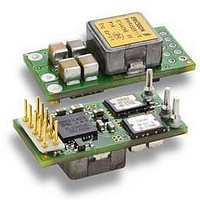
DC/DC Converters & Regulators 66W 4.5-14V OUT 20A 25.65x12.9x8.22 mm
Manufacturer
Ericsson Power Modules
Series
BMR 450r
Datasheet
1.BMR4500002020.pdf
(31 pages)
Specifications of BMR4500002/020
Output Power
110 W
Input Voltage Range
4.5 V to 14 V
Number Of Outputs
1
Output Voltage (channel 1)
0.6 V to 5.5 V
Output Current (channel 1)
20 A
Package / Case Size
25.65 mm x 12.9 mm x 8.2 mm
Output Voltage
0.6 V to 5.5 V
Product
Non-Isolated / POL
Lead Free Status / RoHS Status
Lead free / RoHS Compliant


E
5.0 V, 20 A/100 W Electrical Specification
T
Typical values given at: T
Additional C
Sense pins are connected to the output pins.
Characteristics
V
V
V
P
η
P
P
P
I
V
V
V
t
C
t
t
t
t
I
I
I
V
Note 1: See Operating Information section for External Decoupling Capacitors.
Note 2: See Operating Information section for Output Ripple and Noise.
Note 3: See Operating Information section for Power Management Overview.
Note 4: See Operating Information section for Turn-off Input Voltage Range
Prepared (also subject responsible if other)
EAB/FJB/GMF EKAMAGN
Approved
EAB/FJB/GMF Torbjörn Holmberg
BMR 450 Digital PoL Regulators
Input 4.5-14 V, Output up to 20 A / 100 W
S
tr1
r
s
f
CTRL
O
lim
sc
P1
I
Ioff
Ion
O
d
li
RC
Oi
O
tr1
Oac
O
= -40 to +85ºC, V
I
= 470 µF. See Operating Information section for selection of capacitor types.
Input voltage range
Turn-off input voltage
Turn-on input voltage
Output power
Efficiency
Power dissipation
Input idling power
Input standby power
Static input current
Output voltage initial setting and
accuracy
Output voltage tolerance band
Idling voltage
Line regulation
Load regulation
Load transient
voltage deviation
Load transient recovery time
Recommended capacitive load
Ramp-up time
(from 10 − 90 % of V
Start-up time
(from V
V
(From V
CTRL start-up time
CTRL shut-down fall time
(From CTRL off to 10 % of V
Output current
Current limit threshold
Short circuit current
Output ripple & noise
I
shut-down fall time.
I
connection to 10 % of V
I
I
= 6 to 14 V. Configuration: CDA 102 899/020, R
off to 10 % of V
P1
= +25°C, V
Oi
)
O
I
)
= 12.0 V, max I
Oi
O
)
)
Conditions
Decreasing input voltage, see
Note 4
Increasing input voltage, see
Note 4
50 % of max I
max I
I
Turned off with CTRL, monitoring
enabled, see Note 3
Low power mode, monitoring
disabled, see Note 3
0.05 - 100 % of max I
I
0.05 - 100 % of max I
Load step 25–75-25 % of max I
di/dt = 2.5 A/μs with default
configuration and C
See Note 1
0.05 - 100 % of max I
I
I
See Note 2
O
O
O
O
= 0.01 A
= 0.01 A
= 0.2 A
= 0.2 A
O
Checked
ETORHOL
O
, unless otherwise specified under Conditions.
O
O
O
O
= 2 mF
O
SET
Ericsson Internal
PRODUCT SPECIFICATION
No.
2/1301-BMR 450 0002 Uen
Date
2010-03-02
= 0 Ω.
O
,
4.950
4.925
0.01
min
470
24
6
0
-
-
Technical Specification
EN/LZT 146 400 R3A March 2010
© Ericsson AB
Rev
H
-190/+190
5.000
5.000
4.25
94.0
93.0
120
150
250
250
100
typ
4.5
7.4
1.6
8.9
30
20
10
30
20
40
4
4
7
7
Reference
BMR 450 0002/020
100 000
5.050
5.075
max
100
14
20
-
-
mVp-p
9 (15)
Unit
mW
mW
mV
mV
mV
ms
ms
ms
ms
ms
ms
μ
W
W
W
μ
μ
%
V
V
V
A
V
V
V
A
A
A
12
F
s
s
Related parts for BMR4500002/020
Image
Part Number
Description
Manufacturer
Datasheet
Request
R

Part Number:
Description:
37.5-150W DC/DC POWER MODULES
Manufacturer:
Ericsson Power Modules
Part Number:
Description:
DC/DC Power Supply Dual-OUT 3.3V/5V 9.6A/6.4A 40W 10-Pin
Manufacturer:
Ericsson Power Modules
Part Number:
Description:
DC/DC Power Supply Single-OUT 3.3V 20A 66W 8-Pin Quarter-Brick
Manufacturer:
Ericsson Power Modules
Datasheet:
Part Number:
Description:
DC/DC Power Supply Single-OUT 1.8V 50A 90W 11-Pin
Manufacturer:
Ericsson Power Modules
Part Number:
Description:
Module DC-DC 1-OUT 1.8V 30A 54W 9-Pin
Manufacturer:
Ericsson Power Modules

Part Number:
Description:
Module DC-DC 1-OUT 1.8V 60A 108W 11-Pin Half-Brick
Manufacturer:
Ericsson Power Modules
Datasheet:

Part Number:
Description:
Module DC-DC 1-OUT 12V 25A 300W 11-Pin Half-Brick
Manufacturer:
Ericsson Power Modules
Part Number:
Description:
Module DC-DC 1-OUT 5V 20A 100W Quarter-Brick
Manufacturer:
Ericsson Power Modules

Part Number:
Description:
Module DC-DC 1-OUT 12V 6A 72W 8-Pin 1/8-Brick
Manufacturer:
Ericsson Power Modules
Datasheet:
Part Number:
Description:
Module DC-DC 1-OUT 5.05V 2A 10W 18-Pin SMD
Manufacturer:
Ericsson Power Modules
Part Number:
Description:
Manufacturer:
Ericsson Power Modules
Datasheet:

Part Number:
Description:
Module DC-DC 1-OUT 5V 60A 300W 11-Pin Half-Brick Tray
Manufacturer:
Ericsson Power Modules
Part Number:
Description:
Module DC-DC 1-OUT 12V 1A 12W 18-Pin
Manufacturer:
Ericsson Power Modules
Datasheet:
Part Number:
Description:
Module DC-DC 2-OUT 12V/-12V 0.25A 6W 18-Pin SMD
Manufacturer:
Ericsson Power Modules
Part Number:
Description:
Module DC-DC 1-OUT 28V 11A 310W 11-Pin Half-Brick Tray
Manufacturer:
Ericsson Power Modules
Datasheet: