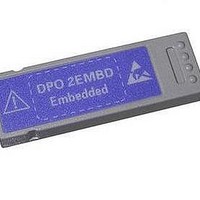
DPO2EMBD Tektronix, DPO2EMBD Datasheet - Page 6

DPO2EMBD
Manufacturer Part Number
DPO2EMBD
Description
Benchtop Oscilloscopes Embd. serial trigger and analysis module
Manufacturer
Tektronix
Type
Embedded Serial Triggering and Analysis Moduler
Datasheet
1.ACD2000.pdf
(11 pages)
Specifications of DPO2EMBD
Equipment Type
Module
Sampling Rate
1 GS/s
Sweep
1 X / 10 X
Bandwidth
200 MHz
Display Type
TFT-LCD Color
Used With
MSO2000 and DPO2000 Series Oscilloscopes
Lead Free Status / RoHS Status
Lead free / RoHS Compliant
6
Digital Phospor Oscilloscopes
MSO2000 Series • DPO2000 Series
1
2
3
4
5
6
Zoom/Pan – Dedicated front panel controls for
zooming and panning. Get from the start to the end
of your 1 M record in seconds. The inner control
adjusts the zoom factor while the outer ring adjust
pans the zoom box across the waveform. Navigating
your waveform has never been easier.
Marks – Want to mark your waveform for future
reference or for quick navigation between events of
interest? Simply press the Set Mark button to place
“bookmarks” on your waveform. Use the Next and
previous buttons to navigate through user marks
and search generated marks.
Search – Tired of turning the horizontal position
control endlessly on your current scope to find the
event you’re looking for? Use the MSO/DPO2000’s
powerful Search feature to automatically find and
mark all occurrences of an event based on user
specified criteria. Search types include edge, pulse
width, runt, logic, multichannel setup and hold,
rise/fall time and I2C, SPI, CAN, LIN, and RS-
232/422/485/UART packet content.
2 or 4 Analog Channels and 16 Digital
Channels – View and trigger on up to 20 time
correlated signals on the same display. (16 Digital
Channels on MSO models only.)
Parallel and Serial Buses – Trigger on parallel
or serial packet level content, view acquired data as a
bus with all data decoded into hex, binary or ASCII,
search through acquisitions for specific content and
even view all decoded data in a tabular format, much
like you would see on a logic analyzer. Standards
supported include I2C, SPI, CAN, LIN, and RS-232/
422/485/UART. Analyze up to two buses at the same
time. (Parallel is available on MSO models only.)
Dedicated Vertical Controls – Vertical
controls provide simple and intuitive operation.
No longer do you need to share one set of
vertical controls across all four channels.
Digital Phosphor Oscilloscopes • www.tektronix.com/mso2000
7
Large Widescreen, Digital Phosphor
Display – The MSO/DPO2000 Series boasts
a bright, 7 inch (180 mm), widescreen display.
Discover and troubleshoot design problems faster
with 5,000 waveforms/second continuous wave-
form capture rate and real time intensity grading.
Continuous high waveform capture rate saves time
by quickly revealing the nature of faults so advanced
triggers can be applied to isolate them. Real time
intensity grading exposes the “history” of a signal’s
activity as they accumulate. The digital phosphor
display makes its easier to understand the charac-
teristics of the transients you have captured. It
intensifies the areas where the signal trace
occurs more frequently.
7
10
8
FilterVu™ Variable Low-Pass Filter –
Tired of dealing with unwanted noise on your
signal? Ever wished your oscilloscope had band-
width limiters below 20 MHz? Simply turn on
FilterVu and adjust the variable low-pass noise
filter. Unlike other variable low pass filters,
FilterVu filters out the unwanted noise from your
signal while still capturing glitches and other
signal details up to the full bandwidth of the
oscilloscope. FilterVu is ideal for repetitive,
single-shot and non-repetitive events.
4
5
9
Serial Trigger and Decode Application
Module – MSO/DPO2000 Series have 2 slots for
application modules. Application specific modules
extend how you use your oscilloscope by adding
serial bus triggering and decode. DPO2AUTO –
Automotive serial bus triggering and decode with
support for CAN and LIN buses. DPO2COMP-
Computer bus serial triggering and decode with
support for RS-232/422/485/UART buses.
DPO2EMBD – Embedded bus serial triggering
and decode with support for I2C and SPI buses.
8
3
10
USB – Use the front-panel USB host port for
simple and convenient storage of screenshots,
waveform data, and oscilloscope setups. Use the
rear-panel USB device port to easily communi-
cate and control your oscilloscope from a PC.
Or use the rear-panel USB device port to directly
print your screen image to any PictBridge
compatible printer.
See the MSO/DPO2000 Series in action for yourself.
Try out the MSO/DPO2000 Virtual Oscilloscope at:
www.tektronix.com/virtualmso2000
1
Digital Phosphor Oscilloscopes • www.tektronix.com/mso2000
11
9
2
®
6
11
Digital Phospor Oscilloscopes
TekVPI
direct-connect current probes, intuitive comp box
controls, remote control of probe settings and
smarter communication between the oscilloscope
and the probe.
Optional LAN and VGA video ports!
- Connect your oscilloscope to your network to
Only 5.3 inches deep!
- Free up valuable space on your bench or desktop.
remotely control and collect data. Display your
screen on an external monitor or projector.
MSO2000 Series • DPO2000 Series
®
– TekVPI probe interface provides for
7


