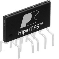
TFS761HG Power Integrations, TFS761HG Datasheet - Page 28

TFS761HG
Manufacturer Part Number
TFS761HG
Description
Switching Converters, Regulators & Controllers 2 Swt Fwd,Flybk Cntr 326 W Cont. @ 25 C
Manufacturer
Power Integrations
Datasheet
1.TFS758HG.pdf
(36 pages)
Specifications of TFS761HG
Output Voltage
100 V to 400 V
Output Power
383 W
Switching Frequency
66 KHz
Operating Temperature Range
+ 150 C
Mounting Style
Through Hole
Duty Cycle (max)
73 %
Package / Case
eSIP-16B
Number Of Outputs
1
Lead Free Status / RoHS Status
Lead free / RoHS Compliant
Available stocks
Company
Part Number
Manufacturer
Quantity
Price
Company:
Part Number:
TFS761HG
Manufacturer:
POWER
Quantity:
15 000
Part Number:
TFS761HG
Manufacturer:
POWER
Quantity:
20 000
NOTES:
A. The current limit is boosted for the first 34 ms of main supply switching and returns to normal level after this period.
B. V
C. Level 1 R
D. Level 1 R
Rev. C 02/11
Standby Circuit Protection (cont.)
ENABLE Pin Current
Limit Selection Range #2
ENABLE Pin Current
Limit Selection Range #3
ENABLE Pin Current
Limit Selection Range #4
Standby Current Limit
General Circuit Protection
Power Coefficient
Initial Current Limit
Leading Edge
Blanking Time (Main)
Leading Edge Blanking
Time (Standby)
Current Limit
Delay (Main)
Current Limit
Delay (Standby)
Thermal Shutdown
Temperature
Thermal Shutdown
Hysteresis
Auto-Restart ON-Time
at f
Auto-Restart Duty
Cycle Standby
Supply Current
DRAIN Supply Current
28
OSC
DDH(SHUNT)
Parameter
Standby
TFS757-764HG
FB
EN
minus V
= open, Level 2 R
= open, Level 2 R
DDH(UV_ON)
is equal to 250 mV minimum.
Symbol
I
I
I
I
I
I
I
T
LIM(2)(DSB)
LIM(3)(DSB)
LIM(4)(DSB)
LIM(1)(DSB)
LIM(2)(DSB)
LIM(3)(DSB)
LIM(4)(DSB)
t
t
LEB(DSB)
DC
Δ I
t
ILD(DSB)
SD(HYST)
t
FB
EN
LEB(D)
T
I
ILD(D)
t
I
I
I
INIT
AR
S1
S2
2
SD
LIM
f
= 511 kW, Level 3 R
= 280 kW, Level 3 R
AR
I
I
I
I
L
L
L
L
SOURCE = 0 V; T
= 20 mA, di/dt = 125 mA/ms, T
= 20 mA, di/dt = 143 mA/ms, T
= 20 mA, di/dt = 105 mA/ms, T
= 20 mA, di/dt = 95 mA/ms, T
I
LIM
(Unless Otherwise Specified)
EN Open (Standby MOSFET
I
2
(I
f = I
(No MOSFETs Switching)
L
= 100 mA) / I
di/dt = 125 mA/ms
LIM(2)(DSB)(TYP)
FB
Switching at f
EN
EN Current > I
Conditions
= 232 kW.
= 137 kW, Level 4 R
T
T
T
T
T
T
T
T
Start-up
Start-up
Start-up
J
J
J
J
J
J
J
J
= 25 °C
= 25 °C
= 25 °C
= 25 °C
= 25 °C
= 25 °C
= 25 °C
= 25 °C
J
= 0 °C to 100 °C
× f
LIM
S(SB)(OSC)(TYP)
(I
OSC
L
DIS
= 20 mA)
)
J
J
J
J
= 25 °C
= 25 °C
= 25 °C
= 25 °C
EN
= 63.4 kW.
0.9 × I
0.75 ×
I
LIM(MIN)
Min
450
600
675
495
170
170
400
600
2
f
8.5-18
18-33
33-60
Typ
500
650
750
550
215
215
150
150
118
750
950
2.2
80
55
64
I
2
f
1.12 × I
1000
1200
Max
550
700
825
605
www.powerint.com
2
f
Units
A
mA
ms
mA
mA
mA
°C
°C
mA
ns
ns
ns
ns
%
2
%
Hz


