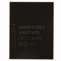
RC48F4400P0TB00A NUMONYX, RC48F4400P0TB00A Datasheet - Page 87

RC48F4400P0TB00A
Manufacturer Part Number
RC48F4400P0TB00A
Description
IC FLASH 512MBIT 85NS 64EZBGA
Manufacturer
NUMONYX
Series
StrataFlash™r
Datasheet
1.RD48F4400P0VBQEJ.pdf
(97 pages)
Specifications of RC48F4400P0TB00A
Format - Memory
FLASH
Memory Type
FLASH
Memory Size
512M (32Mx16)
Speed
85ns
Interface
Parallel
Voltage - Supply
2.3 V ~ 3.6 V
Operating Temperature
-40°C ~ 85°C
Package / Case
64-EZBGA
Lead Free Status / RoHS Status
Contains lead / RoHS non-compliant
Other names
885960
885960
RC48F4400P0TB00885960
885960
RC48F4400P0TB00885960
Available stocks
Company
Part Number
Manufacturer
Quantity
Price
Company:
Part Number:
RC48F4400P0TB00A
Manufacturer:
Micron Technology Inc
Quantity:
10 000
P30
Figure 41: Protection Register Programming Flowchart
A.3
August 2008
Order Number: 306666-12
Address & Data
Register Data
Read Status
Read Status
PR Address
Write 0xC0,
Full Status
(if desired)
Successful
Complete
Write PR
Register
Program
Program
SR[7] =
SR[3] =
SR[4] =
SR[1] =
Check
Start
1
0
0
0
0
1
1
1
Write State Machine
Figure 42
based on incoming commands. Only one partition can be actively programming or
erasing at a time. Each partition stays in its last read state (Read Array, Read Device
ID, Read CFI or Read Status Register) until a new command changes it. The next WSM
state does not depend on the partition’s output state.
(Program Setup)
(Confirm Data)
PROTECTION REGISTER PROGRAMMING PROCEDURE
Register Locked;
Program Aborted
V
Program Error
PP
Range Error
through
FULL STATUS CHECK PROCEDURE
Figure 47
Operation
Program Protection Register operation addresses must be
within the Protection Register address space. Addresses
outside this space will return an error.
Repeat for subsequent programming operations.
Full Status Register check can be done after each program, or
after a sequence of program operations.
Write 0xFF after the last operation to set Read Array state.
Operation
Only the Clear Staus Register command clears SR[1, 3, 4].
If an error is detected, clear the Status register before
attempting a program retry or other error recovery.
show the command state transitions (Next State Table)
Write
Write
Read
Bus
Bus
Idle
Idle
Idle
Idle
Command
Command
Protection
PR Setup
Program
Program
None
None
None
None
None
Data = 0xC0
Addr = First Location to Program
Data = Data to Program
Addr = Location to Program
Status Register Data.
Check SR[7]:
1 = WSM Ready
0 = WSM Busy
Check SR[3]:
1 =V
Check SR[4]:
1 =Programming Error
Check SR[1]:
1 =Block locked; operation aborted
PP
Range Error
Comments
Comments
Datasheet
87


