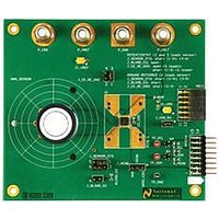
SPIO-4/NOPB National Semiconductor, SPIO-4/NOPB Datasheet - Page 12

SPIO-4/NOPB
Manufacturer Part Number
SPIO-4/NOPB
Description
BOARD INTERFACE FOR AFE
Manufacturer
National Semiconductor
Datasheet
1.SPIO-4NOPB.pdf
(26 pages)
Specifications of SPIO-4/NOPB
Main Purpose
Interface, Analog Front End (AFE)
Embedded
Yes, MCU, 32-Bit
Utilized Ic / Part
SAM3U, XC6SLX16
Primary Attributes
USB Powered or External Supply
Secondary Attributes
GUI, I2C, SPI, USB Interfaces
Accessory Type
Digital Interface Board
Msl
MSL 1 - Unlimited
Lead Free Status / RoHS Status
Lead free / RoHS Compliant
Other names
SPI0-4/NOPB
SPI0-4/NOPB
SPI0-4/NOPB
Available stocks
Company
Part Number
Manufacturer
Quantity
Price
Company:
Part Number:
SPIO-4/NOPB
Manufacturer:
National Semiconductor
Quantity:
135
National Semiconductor
28
29
30
31
32
2.6 Auxiliary Interface
The SPIO-4 Board can be connected to auxiliary test equipment through debug connector J4 located on
the board.
2.7 Computer Interface
The SPIO-4 Board communicates with a PC via standard USB 2.0 at high-speed (up to a 480 Mbits/sec
signaling rate). It is fully backward compatible with USB 1.1 devices and cables.
2.8 Memory
The SPIO-4 Board comes with 8M x 16bits of PSRAM for data storage. It is a single Micron
MT45W8MW16BGX PSRAM configured for asynchronous accesses. In asynchronous configuration the
fastest access speed is 70ns latency or approximately 14.2 MHz per 16 bit transfer. Both the processor
and the FPGA have read/write access to the PSRAM. The processor’s Static Memory Interface
mastership is controlled by firmware with in the processor as there is no hardware mechanism to share
the bus.
2.9 Power Requirements
The SPIO-4 Data Capture Board can be solely powered via the USB interface power but can also be
powered by external power supply. The SPIO-4 Data Capture Board consumes up to 500 mA of current
depending on the DUT load. ADC evaluation boards differ widely in their power consumption – please
consult the manual that came with your evaluation board, and verify if an external supply is required for
your DUT board. External power can be supplied via J10 and must be greater than 4.5V and less than
6.0V DC with a current rating of at least 1A.
Serial Bus B – Data from the slave (device) to the master. The device
may implement this as a tri-state signal that can be driven by multiple
devices on Serial Bus B in a bussed fashion. The pull-up resistor, if
required, is on the DUT board.
Available for implementation specific use. Refer to the DUT
board manual.
If a second SPI bus is implemented, then use this pin as shown:
SCS2_B
SerialBus B – Chip Select for device 2.
Available for implementation specific use. Refer to the DUT
board manual.
If a second SPI bus is implemented, then use this pin as shown:
SMOSI_B
Serial Bus B – Data from the master to the slave (device).
Available for implementation specific use. Refer to the DUT
board manual.
If a second SPI bus is implemented, then use this pin as shown:
SCS3_B~
SerialBus B – Chip Select for device 3.
Reserved for future use. The DUT board shall leave this pin open.
GND
~
If unused, leave it open.
If unused, leave it open.
If unused, leave it open.
Table 4 GPSI-32 Signals
Page 12
3.3V
3.3V
3.3V
3.3V
www.national.com


