ISL59605IRZ-EVALZ Intersil, ISL59605IRZ-EVALZ Datasheet

EVALUATION BOARD FOR ISL5960X

ISL59605IRZ-EVALZ

Manufacturer Part Number
ISL59605IRZ-EVALZ
Description
EVALUATION BOARD FOR ISL5960X
Manufacturer
Intersil
Series
MegaQ™r

Specifications of ISL59605IRZ-EVALZ

Main Purpose
Video, Cable Equalizer/Amplifier
Embedded
No
Utilized Ic / Part
ISL59605IRZ
Secondary Attributes
LED Status Indicators
Lead Free Status / RoHS Status
Lead free / RoHS Compliant
Primary Attributes
-
ISL59605IRZ-EVALZ Evaluation Board Operation
Description
The ISL59605IRZ-EVALZ board is designed to allow evaluation of
the ISL5960x (“MegaQ™”) family of parts, as well as provide the
reference schematic and PCB layout of a typical MegaQ™
application.
Power Connections
The power connectors are at the middle of the top of the
evaluation board. The board requires a 5V power supply capable
of supplying at least 110mA. Because of the high amount of
high-frequency gain required to equalize long cables, excessive
noise on the power supply may introduce noise on the output
signal or cause difficulty locking at longer distances. Power
supplies with linear regulators are preferable to switching
regulators, however, switching supplies may work acceptably
well if they are adequately filtered.
Input Connections
Unshielded twisted pair (UTP) signals arrive via the RJ-45 Cat 5
connector on the left. The input signal can arrive on any arbitrary
combination of pins, though it would typically be one of the
standard Cat x pairs of 1 and 2, 3 and 6, 4 and 5, or 7 and 8. The
3x8 jumper block to the right of the RJ-45 jack is used to assign
which Cat x pin goes to the positive MegaQ™ input (in the photo,
it’s pin 8), and which goes to the negative input (pin 7). The
“Termination” switch to the lower right of the jumper block
January 21, 2011
AN1598.1
1
1-888-INTERSIL or 1-888-468-3774
Intersil (and design) and MegaQ are trademarks owned by Intersil Corporation or one of its subsidiaries.
CAUTION: These devices are sensitive to electrostatic discharge; follow proper IC Handling Procedures.
should be switched to “CAT5” (it’s set to “COAX” in the photo). Do
not attach a coax cable while trying to receive a signal over Cat x.
Coax signals are connected through the “COAX IN” BNC
connector on the upper left. When using coax signals, set the
“Termination” switch to “COAX” and ensure that no Cat x cables
are attached to the RJ45 connector.
The IN+ and IN- test points near U1 can be used to view the input
signals at the input to the MegaQ™ chip.
Output Connections
Standard 75Ω composite video is available at the “VIDEO OUT”
BNC connector on the right, as well as the “OUT” test pin between
U1 and the BNC output.
Switch Settings
There are several switches on the evaluation board that can be
used to put MegaQ™ in its different operational modes:
• “EQ DIS” (EQ Enable): This can be used to disable the EQ so
• COLOR: The Color signal can be an input or an output (see
that an external source can drive a signal over the cable. This
switch should be set to 0 for normal operation (switch in “up”
position). Note: The switch used may have a middle “open”
position, but it should always be set low or high.
datasheet for more information). The default position for
automatic color detection is the middle position (“F” for floating,
not 0 or 1).
All other trademarks mentioned are the property of their respective owners.
|
Copyright Intersil Americas Inc. 2010, 2011. All Rights Reserved
Application Note 1598
Author: Fred Hamilton

Related parts for ISL59605IRZ-EVALZ

ISL59605IRZ-EVALZ Summary of contents

Page 1

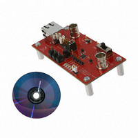
... ISL59605IRZ-EVALZ Evaluation Board Operation Description The ISL59605IRZ-EVALZ board is designed to allow evaluation of the ISL5960x (“MegaQ™”) family of parts, as well as provide the reference schematic and PCB layout of a typical MegaQ™ application. Power Connections The power connectors are at the middle of the top of the evaluation board ...

Page 2

INVERT: The Invert signal can be an input or an output (see datasheet for more info). The default position for automatic inversion detection and correction is the middle position (“F” for floating - not 0 or 1). • FREEZE: ...

Page 3

... ISL59605IRZ-EVALZ Evaluation Board Schematic ...

Page 4

... ISL59605IRZ-EVALZ Board Layout 4 Application Note 1598 FIGURE 1. PCB TOP LAYER WITH SILKSCREEN FIGURE 2. PCB BOTTOM LAYER WITH SILKSCREEN January 21, 2011 AN1598.1 ...

Page 5

... ISL59605IRZ-EVALZ Board Layout 5 Application Note 1598 (Continued) FIGURE 3. PCB TOP LAYER FIGURE 4. PCB BOTTOM LAYER January 21, 2011 AN1598.1 ...

Page 6

... SW2, SW3, SW4 Intersil Corporation reserves the right to make changes in circuit design, software and/or specifications at any time without notice. Accordingly, the reader is cautioned to verify that the Application Note or Technical Brief is current before proceeding. For information regarding Intersil Corporation and its products, see www.intersil.com ...

Related keywords