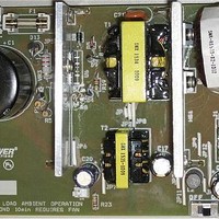
RDK-249 Power Integrations, RDK-249 Datasheet - Page 2

RDK-249
Manufacturer Part Number
RDK-249
Description
KIT REF DESIGN PFS762HG
Manufacturer
Power Integrations
Series
HiperTFS®r
Specifications of RDK-249
Main Purpose
Reference Design, PC Power Supply
Embedded
No
Utilized Ic / Part
TFS762HG
Primary Attributes
12V 25A, 5V 2.9A Outputs, 300 ~ 385 VDC Input
Output Voltage
5 V
Input / Supply Voltage (max)
385 VDC
Input / Supply Voltage (min)
300 VDC
Duty Cycle (max)
50 %
Mounting Style
Through Hole
Output Current
2.9 A
Output Power
14.5 W
Lead Free Status / RoHS Status
Lead free / RoHS Compliant
Secondary Attributes
-
Other names
596-1398
Table of Contents
1
2
3
4
5
6
7
8
9
10
11
12
13
4.1
4.2
4.3
4.4
4.5
7.1
7.2
7.3
7.4
7.5
8.1
8.2
8.3
8.4
8.5
9.1
9.2
9.3
9.4
9.5
11.1
11.2
11.3
11.4
11.5
13.1
13.2
13.3
Introduction.................................................................................................................4
Power Supply Specification ........................................................................................5
Schematic...................................................................................................................6
Circuit Description ......................................................................................................7
PCB Layout ..............................................................................................................10
Bill of Materials .........................................................................................................12
Standby Transformer Specification...........................................................................15
Main Transformer Specification ................................................................................17
Main Output Inductor Specification...........................................................................20
11.5.1
11.5.2
11.5.3
Transformer Design Spreadsheet .........................................................................21
Performance Data.................................................................................................27
Thermal Performance ...........................................................................................34
Waveforms............................................................................................................35
Power Input and Filter .........................................................................................7
Primary Side........................................................................................................7
Output Rectification .............................................................................................8
Output Feedback.................................................................................................9
Output Overvoltage Protection ............................................................................9
Electrical Diagram .............................................................................................15
Electrical Specifications.....................................................................................15
Materials............................................................................................................15
Transformer Build Diagram ...............................................................................16
Transformer Construction..................................................................................16
Electrical Diagram .............................................................................................17
Electrical Specifications.....................................................................................17
Materials............................................................................................................17
Transformer Build Diagram ...............................................................................18
Transformer Construction..................................................................................19
Electrical Diagram .............................................................................................20
Electrical Specifications.....................................................................................20
Materials............................................................................................................20
Winding Instructions ..........................................................................................20
Inductor Illustrations ..........................................................................................20
Main and Standby Efficiency .............................................................................27
Full Power Standby Efficiency vs. Equivalent AC Input Voltage........................28
Standby Efficiency vs. Output Power ................................................................29
Standby Only No-Load Input Power ..................................................................30
Main and Standby Voltage Regulation ..............................................................31
Main Drain Voltage and Current, Normal Operation, Full Power .......................35
Standby Drain Voltage and Current, Normal Operation, Full Power..................36
Standby Drain Current and Output Voltage Start-Up Profile..............................37
Power Integrations, Inc.
Tel: +1 408 414 9200 Fax: +1 408 414 9201
www.powerint.com
Main Load Regulation ................................................................................31
Standby Load Regulation at Equivalent AC Input Voltages........................32
Standby Line Regulation at Full Power ......................................................33
Page 2 of 48


