EVAL-ADF4360-5EBZ1 Analog Devices Inc, EVAL-ADF4360-5EBZ1 Datasheet - Page 18
EVAL-ADF4360-5EBZ1
Manufacturer Part Number
EVAL-ADF4360-5EBZ1
Description
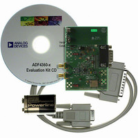
BOARD EVALUATION FOR ADF4360-5
Manufacturer
Analog Devices Inc
Datasheet
1.ADF4360-5BCPZ.pdf
(24 pages)
Specifications of EVAL-ADF4360-5EBZ1
Main Purpose
Timing, Frequency Synthesizer
Embedded
No
Utilized Ic / Part
ADF4360-5
Primary Attributes
Single Integer-N PLL with VCO
Secondary Attributes
1.3GHz, 200kHz PFD
Lead Free Status / RoHS Status
Lead free / RoHS Compliant


ADF4360-5
CONTROL LATCH
With (C2, C1) = (0, 0), the control latch is programmed. Table 7
shows the input data format for programming the control latch.
Prescaler Value
In the ADF4360 family, P2 and P1 in the control latch set the
prescaler values.
Power-Down
DB21 (PD2) and DB20 (PD1) provide programmable power-
down modes.
In the programmed asynchronous power-down, the device
powers down immediately after latching a 1 into Bit PD1, with
the condition that PD2 has been loaded with a 0. In the pro-
grammed synchronous power-down, the device power-down is
gated by the charge pump to prevent unwanted frequency
jumps. Once the power-down is enabled by writing a 1 into
Bit PD1 (on the condition that a 1 has also been loaded to PD2),
the device goes into power-down on the second rising edge of
the R counter output, after LE goes high. When the CE pin is
low, the device is immediately disabled regardless of the state of
PD1 or PD2.
When a power-down is activated (either synchronous or
asynchronous mode), the following events occur:
• All active dc current paths are removed.
• The R, N, and timeout counters are forced to their load
• The charge pump is forced into three-state mode.
• The digital lock detect circuitry is reset.
• The RF outputs are debiased to a high impedance state.
• The reference input buffer circuitry is disabled.
• The input register remains active and capable of loading and
state conditions.
latching data.
Rev. A | Page 18 of 24
Charge Pump Currents
CPI3, CPI2, and CPI1 in the ADF4360 family determine
Current Setting 1.
CPI6, CPI5, and CPI4 determine Current Setting 2. See the
truth table in Table 7.
Output Power Level
Bits PL1 and PL2 set the output power level of the VCO. See the
truth table in Table 7.
Mute-Till-Lock Detect
DB11 of the control latch in the ADF4360 family is the mute-till-
lock detect bit. This function, when enabled, ensures that the RF
outputs are not switched on until the PLL is locked.
CP Gain
DB10 of the control latch in the ADF4360 family is the charge
pump gain bit. When it is programmed to 1, Current Setting 2 is
used. When it is programmed to 0, Current Setting 1 is used.
Charge Pump Three-State
This bit puts the charge pump into three-state mode when
programmed to a 1. It should be set to 0 for normal operation.
Phase Detector Polarity
The PDP bit in the ADF4360 family sets the phase detector
polarity. The positive setting enabled by programming a 1 is
used when using the on-chip VCO with a passive loop filter or
with an active noninverting filter. It can also be set to 0, which is
required if an active inverting loop filter is used.
MUXOUT Control
The on-chip multiplexer is controlled by M3, M2, and M1.
See the truth table in Table 7.
Counter Reset
DB4 is the counter reset bit for the ADF4360 family. When this
is 1, the R counter and the A, B counters are reset. For normal
operation, this bit should be 0.
Core Power Level
PC1 and PC2 set the power level in the VCO core. The recom-
mended setting is 10 mA. See the truth table in Table 7.
Related parts for EVAL-ADF4360-5EBZ1
Image
Part Number
Description
Manufacturer
Datasheet
Request
R

Part Number:
Description:
±1.7g Dual-Axis IMEMS Accelerometer Evaluation Board
Manufacturer:
Analog Devices Inc
Datasheet:

Part Number:
Description:
Inertial Sensor Evaluation System
Manufacturer:
Analog Devices Inc
Datasheet:
Part Number:
Description:
Manufacturer:
Analog Devices Inc
Datasheet:
Part Number:
Description:
Manufacturer:
Analog Devices Inc
Datasheet:
Part Number:
Description:
Manufacturer:
Analog Devices Inc
Datasheet:
Part Number:
Description:
Manufacturer:
Analog Devices Inc
Datasheet:
Part Number:
Description:
Manufacturer:
Analog Devices Inc
Datasheet:
Part Number:
Description:
Manufacturer:
Analog Devices Inc
Datasheet:
Part Number:
Description:
Manufacturer:
Analog Devices Inc
Datasheet:
Part Number:
Description:
Manufacturer:
Analog Devices Inc
Datasheet:
Part Number:
Description:
Manufacturer:
Analog Devices Inc
Datasheet:
Part Number:
Description:
Manufacturer:
Analog Devices Inc
Datasheet:
Part Number:
Description:
Manufacturer:
Analog Devices Inc
Datasheet: