CP2110EK Silicon Laboratories Inc, CP2110EK Datasheet - Page 2
CP2110EK
Manufacturer Part Number
CP2110EK
Description
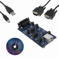
KIT EVAL FOR CP2110
Manufacturer
Silicon Laboratories Inc
Specifications of CP2110EK
Main Purpose
Interface, USB 2.0 to UART (RS485) Bridge
Embedded
No
Utilized Ic / Part
CP2110
Primary Attributes
Full Speed (12Mbps)
Secondary Attributes
LED Status Indicators
Interface Type
RS-232, USB
Operating Supply Voltage
3.3 V
Product
Interface Development Tools
For Use With/related Products
CP2110
Lead Free Status / RoHS Status
Lead free / RoHS Compliant
Lead Free Status / RoHS Status
Lead free / RoHS Compliant
Other names
336-2003
Available stocks
Company
Part Number
Manufacturer
Quantity
Price
Company:

Part Number:
CP2110EK
Manufacturer:
SiliconL
Quantity:
16


CP2110-EK
4. CP2110 Windows Application
The HIDUart application is an example application that uses the Windows CP2110 HID-to-UART DLL to transmit
and receive data with the CP2110. The application also has access to the CP2110’s GPIO pins. The HIDUart
application is installed as part of the CD installation process. The following steps describe how to start the
application and use some of the features.
2
1.
2.
3.
4.
5.
6.
7.
Ensure that the hardware is connected to a Windows PC as shown in Section 3. If the device is properly connected,
the red SUSPEND LED on the CP2110 evaluation board will turn on.
Launch the HIDUart application, which is found by clicking StartAll ProgramsSilicon LaboratoriesHIDUart
Example.
In the application, configure the baud rate, data bits, parity, stop bits, and type of flow control using the drop-down
menus. This configuration should match the communication settings used by the serial device.
Click Connect to start communication between the application and the CP2110 evaluation board. Once connected, the
USB descriptors retrieved from the device are shown under “Device Information.”
Type data in the Transmit text box and click Transmit to send data from the PC to the serial device.
Send data from serial device to the PC. Any data sent by the serial device to the PC is automatically updated in the
Receive text box.
The HIDUart example automatically recognizes how the GPIO pins are configured and enables/disables the ability to
change and read the pin. The default configuration is shown in Figure 2. Use the Get and Set buttons to read and write
the GPIO pins’ latch values. For GPIO pins that are configured as outputs, setting the pin to logic low ‘0’ will turn on the
corresponding LED on the CP2110 evaluation board.
Figure 2. HIDUart Example Application after Connection
Rev. 0.2
Related parts for CP2110EK
Image
Part Number
Description
Manufacturer
Datasheet
Request
R

Part Number:
Description:
QFN 24/I°/HID USB TO UART BRIDGE
Manufacturer:
Silicon Laboratories Inc

Part Number:
Description:
IC HID USB-TO-UART BRIDGE 24QFN
Manufacturer:
Silicon Laboratories Inc
Datasheet:

Part Number:
Description:
Peripheral Drivers & Components (PCIs) HID USB-UART bridge
Manufacturer:
Silicon Laboratories Inc
Datasheet:
Part Number:
Description:
SMD/C°/SINGLE-ENDED OUTPUT SILICON OSCILLATOR
Manufacturer:
Silicon Laboratories Inc
Part Number:
Description:
Manufacturer:
Silicon Laboratories Inc
Datasheet:
Part Number:
Description:
N/A N/A/SI4010 AES KEYFOB DEMO WITH LCD RX
Manufacturer:
Silicon Laboratories Inc
Datasheet:
Part Number:
Description:
N/A N/A/SI4010 SIMPLIFIED KEY FOB DEMO WITH LED RX
Manufacturer:
Silicon Laboratories Inc
Datasheet:
Part Number:
Description:
N/A/-40 TO 85 OC/EZLINK MODULE; F930/4432 HIGH BAND (REV E/B1)
Manufacturer:
Silicon Laboratories Inc
Part Number:
Description:
EZLink Module; F930/4432 Low Band (rev e/B1)
Manufacturer:
Silicon Laboratories Inc
Part Number:
Description:
I°/4460 10 DBM RADIO TEST CARD 434 MHZ
Manufacturer:
Silicon Laboratories Inc
Part Number:
Description:
I°/4461 14 DBM RADIO TEST CARD 868 MHZ
Manufacturer:
Silicon Laboratories Inc
Part Number:
Description:
I°/4463 20 DBM RFSWITCH RADIO TEST CARD 460 MHZ
Manufacturer:
Silicon Laboratories Inc
Part Number:
Description:
I°/4463 20 DBM RADIO TEST CARD 868 MHZ
Manufacturer:
Silicon Laboratories Inc
Part Number:
Description:
I°/4463 27 DBM RADIO TEST CARD 868 MHZ
Manufacturer:
Silicon Laboratories Inc