EVL90WADP-LLCSR STMicroelectronics, EVL90WADP-LLCSR Datasheet - Page 7
EVL90WADP-LLCSR
Manufacturer Part Number
EVL90WADP-LLCSR
Description
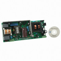
EVAL BOARD PORTABLE PWR SUPPLY
Manufacturer
STMicroelectronics
Type
Power Factor Correctionr
Datasheets
1.L6563HTR.pdf
(49 pages)
2.L6599ADTR.pdf
(36 pages)
3.EVL90WADP-LLCSR.pdf
(29 pages)
4.EVL90WADP-LLCSR.pdf
(28 pages)
Specifications of EVL90WADP-LLCSR
Main Purpose
AC/DC, Primary and Secondary Side with PFC
Outputs And Type
1, Isolated
Power - Output
90W
Voltage - Output
19V
Current - Output
4.75A
Voltage - Input
90 ~ 264VAC
Regulator Topology
Boost
Frequency - Switching
130kHz
Board Type
Fully Populated
Utilized Ic / Part
L6563H, L6599A, SRK2000
Input Voltage
90 V to 264 V
Output Voltage
19 V
Dimensions
65 mm x 155 mm
Product
Power Management Modules
Supply Current
4.75 A
Lead Free Status / RoHS Status
Lead free / RoHS Compliant
For Use With/related Products
L6563H, L6599A, SRK2000
Other names
497-10377


AN3014
Main characteristics and circuit description
L6599A overload and short-circuit protection
The current into the primary winding is sensed by the lossless circuit R41, C27, D11, D10,
R39, and C25 and is fed to the ISEN pin (pin 6). In case of overcurrent, the voltage on the
pin passes an internal threshold (0.8 V), triggering a protection sequence. The capacitor
(C45) connected to the DELAY pin (pin 2) is charged by an internal 150-µA current
generator and is slowly discharged by the external resistor (R24). If the voltage on the pin
reaches 2 V, the soft-start capacitor is completely discharged so that the switching
frequency is pushed to its maximum value. As the voltage on the pin exceeds 3.5 V, the IC
stops switching and the internal generator is turned off, so that the voltage on the pin decays
due to the external resistor. The IC is soft-restarted as the voltage drops below 0.3 V. In this
way, under short-circuit conditions, the converter works intermittently with very low input
average power.
Overvoltage and open loop protection
Both the PFC and resonant circuit stages are equipped with their own overvoltage
protection.
The PFC controller L6563H monitors its output voltage via the resistor divider connected to
a dedicated pin (PFC_OK, pin 7), protecting the circuit in case of loop failures,
disconnection or deviation from the nominal value of the feedback loop divider. If the voltage
on pin #7 exceeds 2.5 V the IC stops switching and restarts as the voltage on the pin falls
below 2.4 V, preventing the output voltage becoming excessive in case of transient due to
the slow response of the error amplifier. However, if contemporaneously the voltage of the
INV pin falls below 1.66 V (typ.), a feedback failure is assumed. In this case the PFC_OK
circuitry latches the L6563H operations and, by means of the PWM_LATCH pin (pin 8) it
latches the L6599A as well, via the DIS pin (pin 8). The converter is kept latched by the
L6563H HV circuit which supplies the IC, charging the V
capacitor periodically. To resume
CC
converter operation, mains restart is necessary.
The DIS pin is used to protect also the resonant stage against overvoltage. The Zener diode
D8 detects the auxiliary voltage, which is proportional to the output voltage. In case of loop
failure it conducts and voltage on the DIS pin exceeds the internal threshold, and latches off
the device. L6563H operation is also stopped by the PFC_STOP pin.
Secondary-side synchronous rectification with the SRK2000
The SRK2000 core function is to switch on each synchronous rectifier MOSFET whenever
the corresponding transformer half-winding starts conducting (i.e. when the MOSFET body
diode starts conducting), and then to switch it off when the current flowing through it
approaches zero. For this purpose, the IC is equipped with two pins (DVS1 and DVS2)
capable of sensing the MOSFET drain voltage level.
Standby power saving
The board has a burst-mode function implemented, allowing power saving during light load
operation.
The L6599A STBY pin (pin 5) senses the optocoupler’s collector voltage, which is related to
the feedback control. This signal is compared to an internal reference (1.24 V). If the voltage
on the pin is lower than the reference, the IC enters an idle state and its quiescent current is
reduced. As the voltage exceeds the reference by 50 mV, the controller restarts the
switching. The burst-mode operation load threshold can be programmed by properly
choosing the resistor connecting the optocoupler to the RFMIN pin (R34). On this board, the
controller operates in burst-mode if the load falls below ~10 W.
Doc ID 16064 Rev 2
7/29
Related parts for EVL90WADP-LLCSR
Image
Part Number
Description
Manufacturer
Datasheet
Request
R

Part Number:
Description:
STMicroelectronics [RIPPLE-CARRY BINARY COUNTER/DIVIDERS]
Manufacturer:
STMicroelectronics
Datasheet:
Part Number:
Description:
STMicroelectronics [LIQUID-CRYSTAL DISPLAY DRIVERS]
Manufacturer:
STMicroelectronics
Datasheet:

Part Number:
Description:
BOARD EVAL FOR MEMS SENSORS
Manufacturer:
STMicroelectronics
Datasheet:
Part Number:
Description:
NPN TRANSISTOR POWER MODULE
Manufacturer:
STMicroelectronics
Datasheet:
Part Number:
Description:
TURBOSWITCH ULTRA-FAST HIGH VOLTAGE DIODE
Manufacturer:
STMicroelectronics
Datasheet:
Part Number:
Description:
Manufacturer:
STMicroelectronics
Datasheet:
Part Number:
Description:
DIODE / SCR MODULE
Manufacturer:
STMicroelectronics
Datasheet:
Part Number:
Description:
DIODE / SCR MODULE
Manufacturer:
STMicroelectronics
Datasheet:
Part Number:
Description:
Search -----> STE16N100
Manufacturer:
STMicroelectronics
Datasheet:
Part Number:
Description:
Search ---> STE53NA50
Manufacturer:
STMicroelectronics
Datasheet:
Part Number:
Description:
NPN Transistor Power Module
Manufacturer:
STMicroelectronics
Datasheet:
Part Number:
Description:
DIODE / SCR MODULE
Manufacturer:
STMicroelectronics
Datasheet: