EVL90WADP-LLCSR STMicroelectronics, EVL90WADP-LLCSR Datasheet
EVL90WADP-LLCSR
Specifications of EVL90WADP-LLCSR


Related parts for EVL90WADP-LLCSR


EVL90WADP-LLCSR Summary of contents
Page 1
... resonant converter with synchronous rectification Introduction This application note describes the characteristics and the features demonstration board (EVL90WADP-LLCSR), tailored to specifications for a typical high-end portable computer power supply. A peculiarity of this SMPS design is the very high efficiency compliant with ENERGY STAR in achieving this result is the SRK2000. This synchronous rectification driver for LLC resonant converters allows significantly reduced secondary-side losses ...
Page 2
Contents Contents 1 Main characteristics and circuit description . . . . . . . . . . . . . . . . . . . . . 5 2 Efficiency measurement . . . . . . . ...
Page 3
... List of tables Table 1. Overall efficiency . . . . . . . . . . . . . . . . . . . . . . . . . . . . . . . . . . . . . . . . . . . . . . . . . . . . . . . . . 9 Table 2. Efficiency comparison . . . . . . . . . . . . . . . . . . . . . . . . . . . . . . . . . . . . . . . . . . . . . . . . . . . . . . 9 Table 3. Light load efficiency . . . . . . . . . . . . . . . . . . . . . . . . . . . . . . . . . . . . . . . . . . . . . . . . . . . . . . 10 Table 4. Thermal map reference points . . . . . . . . . . . . . . . . . . . . . . . . . . . . . . . . . . . . . . . . . . . . . . 16 Table 5. EVL90WADP-LLCSR demonstration board bill of material . . . . . . . . . . . . . . . . . . . . . . . . 18 Table 6. PFC coil winding data . . . . . . . . . . . . . . . . . . . . . . . . . . . . . . . . . . . . . . . . . . . . . . . . . . . . . 23 Table 7. Transformer winding data . . . . . . . . . . . . . . . . . . . . . . . . . . . . . . . . . . . . . . . . . . . . . . . . . . 25 Table 8. Document revision history . . . . . . . . . . . . . . . . . . . . . . . . . . . . . . . . . . . . . . . . . . . . . . . . . 27 Doc ID 16064 Rev 1 List of tables 3/28 ...
Page 4
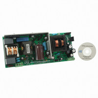
... List of figures List of figures Figure 1. EVL90WADP-LLCSR adapter demonstration board . . . . . . . . . . . . . . . . . . . . . . . . . 1 Figure 2. Electrical diagram . . . . . . . . . . . . . . . . . . . . . . . . . . . . . . . . . . . . . . . . . . . . . . . . . . . . . . . . . 8 Figure 3. Light load efficiency diagram . . . . . . . . . . . . . . . . . . . . . . . . . . . . . . . . . . . . . . . . . . . . . . . 10 Figure 4. Compliance to EN61000-3-2 at 230 Vac - 50 Hz, full load . . . . . . . . . . . . . . . . . . . . . . . . . 11 Figure 5. Compliance to JEITA-MITI at 100 Vac - 50 Hz, full load Figure 6. Resonant stage oscillator at 230 full load . . . . . . . . . . . . . . . . . . . . . . . . . . . . . 12 Figure 7. ...
Page 5
AN3014 1 Main characteristics and circuit description The main features of the SMPS are: Universal input mains range: 90 − 264 Vac, frequency 45 − ● ● Output voltage 4.75 A continuous operation ● Mains ...
Page 6
Main characteristics and circuit description order to avoid capacitive mode operation, but to allow the resonant stage to operate even in case of mains sag and consequent PFC output dip. Fast voltage feed-forward The voltage on the L6563H VFF pin ...
Page 7
AN3014 L6599A overload and short-circuit protection The current into the primary winding is sensed by the lossless circuit R41, C27, D11, D10, R39, and C25 and is fed to the ISEN pin (pin 6). In case of overcurrent, the voltage ...
Page 8
Main characteristics and circuit description In order to achieve better load transient response, the PFC burst-mode operation is partially forced by the resonant converter: as soon as the L6599A stops switching due to load drops, its PFC_STOP pin pulls down ...
Page 9
... In Table 2, the efficiency of two different designs are compared. One is the EVL90WADP- LLCSR board, and the other is an identical board but with diode rectification (two STPS10L60 devices). In this way, a direct indication of the efficiency improvement obtained with the new synchronous rectification solution is obtained. ...
Page 10
Efficiency measurement Light load operation efficiency Measurement results are reported in efficiency is better than 68% even for very light loads, such Table 3. Light load efficiency 230 Test Vout Iout [V] [mA] ...
Page 11
AN3014 3 Harmonic content measurement The board has been tested according to the European standard EN61000-3-2 class-D and Japanese standard JEITA-MITI Class-D, at both nominal input voltage mains. As reported in graphs that follow, the circuit is capable of reducing ...
Page 12
Functional check 4 Functional check Figure 6 and Figure 7 operation. The selected switching frequency is approximately 100 kHz in order to achieve a good trade-off between transformer losses and dimensions. The converter operates above the resonance frequency. turned on ...
Page 13
AN3014 Figure 8. Secondary waveforms at 230 Standby and no-load operation In Figure 10 and the L6599A and L6563H operate in burst-mode. In PFC and LLC bursts are synchronised. Figure 10. No load operation at 230 ...
Page 14
Functional check Figure 12. Transition full load to no load at 265 Vac - 50 Hz Overcurrent and short-circuit protection The L6599A is equipped with a current sensing input (pin 6, ISEN) and a dedicated overcurrent management system. The current ...
Page 15
AN3014 Figure 14. Short-circuit at full load and 115 Vac - the graphs above it can be noted that the average output current as well as the average primary current are limited, preventing converter over-heating and consequent ...
Page 16
Thermal map 5 Thermal map In order to check design reliability, thermal mapping by means camera was done. Below, thermal measurements of the component side of the board at nominal input voltage are shown. The pointers on ...
Page 17
AN3014 6 Conducted emission pre-compliance test The following figures represent the average measurement of the conducted noise at full load and nominal mains voltages. The limits shown on the diagrams are those of the EN55022 class-B standard, which is most ...
Page 18
... Bill of material 7 Bill of material Table 5. EVL90WADP-LLCSR demonstration board bill of material Des. Part type/part value C1 470 470 nF C5 470 100 µ µF C10 1 nF C11 2.2 nF C12 1 µF C13 680 nF C14 68 nF C15 47 µF C16 2.2 nF C17 470 pF C18 2.2 µ ...
Page 19
... AN3014 Table 5. EVL90WADP-LLCSR demonstration board bill of material (continued) Des. Part type/part value C34 220 nF C36 1 µF C39 100 nF C40 100 nF C41 100 nF C42 100 nF C43 4.7 nF C44 10 nF C45 220 nF C48 10 µF D1 GBU4J D2 LL4148 D3 1N4005 D4 STTH2L06 D5 LL4148 D7 LL4148 D8 BZV55-B27 D9 STPS1L60A D10 ...
Page 20
... Bill of material Table 5. EVL90WADP-LLCSR demonstration board bill of material (continued) Des. Part type/part value Q4 STP8NM50FP Q5 BC847C Q6 BC847C Q9 BC847C Q11 STF60N55F3 Q12 STF60N55F3 R1 3.3 MΩ R2 3.3 MΩ MΩ R4 2.2 MΩ 10 Ω NTC 2R5-S237 R7 1 MΩ MΩ kΩ R10 27 kΩ R11 2.2 MΩ ...
Page 21
... AN3014 Table 5. EVL90WADP-LLCSR demonstration board bill of material (continued) Des. Part type/part value R31 15 kΩ 47 Ω R32 R34 3.3 kΩ R35 180 kΩ R37 220 kΩ 56 Ω R38 130 Ω R39 0.0 Ω R40 100 Ω R41 R42 4.7 kΩ 51 Ω ...
Page 22
... Bill of material Table 5. EVL90WADP-LLCSR demonstration board bill of material (continued) Des. Part type/part value R78 33 kΩ R79 150 kΩ 0.0 Ω R80 T1 1860.0025 U1 L6563H U3 SFH617A-2 U4 TL431AIZ U5 SRK2000 U6 L6599A 22/28 Description SMD film res - 1 250 ppm/°C SMD film res - 1 250 ppm/°C SMD film res - 1 250 ppm/° ...
Page 23
AN3014 8 PFC coil specification General description and characteristics ● Application type: consumer, home appliance ● Transformer type: open ● Coil former: vertical type, 6+6 pins ● Max. temperature rise: 45 °C ● Max. operating ambient temperature: 60 °C ● ...
Page 24
PFC coil specification Mechanical aspect and pin numbering ● Maximum height from PCB ● Coil former type: vertical, 6+6 pins (pins 10, 12 are removed) ● Pin distance: 3.81 mm ● Row distance: ...
Page 25
AN3014 9 Transformer specification General description and characteristics ● Application type: consumer, home appliance ● Transformer type: open ● Coil former: horizontal type, 7+7 pins, two slots ● Max. temperature rise: 45 °C ● Max. operating ambient temperature: 60 °C ...
Page 26
Transformer specification Mechanical aspect and pin numbering ● Maximum height from PCB ● Coil former type: horizontal, 7+7 pins (pins 1 and 7 are removed) ● Pin distance: 5.08 mm ● Row distance: 25.4 mm Figure 23. Transformer ...
Page 27
AN3014 10 Revision history Table 8. Document revision history Date 22-Mar-2010 Revision 1 Initial release. Doc ID 16064 Rev 1 Revision history Changes 27/28 ...
Page 28
... Information in this document is provided solely in connection with ST products. STMicroelectronics NV and its subsidiaries (“ST”) reserve the right to make changes, corrections, modifications or improvements, to this document, and the products and services described herein at any time, without notice. All ST products are sold pursuant to ST’s terms and conditions of sale. ...