EVL90WADP-LLCSR STMicroelectronics, EVL90WADP-LLCSR Datasheet - Page 6
EVL90WADP-LLCSR
Manufacturer Part Number
EVL90WADP-LLCSR
Description
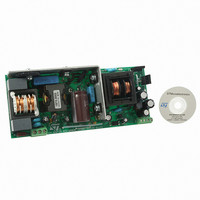
EVAL BOARD PORTABLE PWR SUPPLY
Manufacturer
STMicroelectronics
Type
Power Factor Correctionr
Datasheets
1.L6563HTR.pdf
(49 pages)
2.L6599ADTR.pdf
(36 pages)
3.EVL90WADP-LLCSR.pdf
(29 pages)
4.EVL90WADP-LLCSR.pdf
(28 pages)
Specifications of EVL90WADP-LLCSR
Main Purpose
AC/DC, Primary and Secondary Side with PFC
Outputs And Type
1, Isolated
Power - Output
90W
Voltage - Output
19V
Current - Output
4.75A
Voltage - Input
90 ~ 264VAC
Regulator Topology
Boost
Frequency - Switching
130kHz
Board Type
Fully Populated
Utilized Ic / Part
L6563H, L6599A, SRK2000
Input Voltage
90 V to 264 V
Output Voltage
19 V
Dimensions
65 mm x 155 mm
Product
Power Management Modules
Supply Current
4.75 A
Lead Free Status / RoHS Status
Lead free / RoHS Compliant
For Use With/related Products
L6563H, L6599A, SRK2000
Other names
497-10377


Main characteristics and circuit description
6/28
order to avoid capacitive mode operation, but to allow the resonant stage to operate even in
case of mains sag and consequent PFC output dip.
Fast voltage feed-forward
The voltage on the L6563H VFF pin (pin 5) is the peak value of the voltage on the MULT pin
(pin 3). The RC network (R15+R26, C12) connected to VFF completes the peak-holding
circuit. This signal is necessary to derive RMS input voltage information to compensate the
loop gain, which is mains voltage dependent.
Generally speaking, if the time constant is too small, the voltage generated is affected by a
considerable amount of ripple at twice the mains frequency, thus causing distortion of the
current reference (resulting in high THD and poor PF). If the time constant is too large, there
is a considerable delay in setting the right amount of feed-forward, resulting in excessive
overshoot or undershoot of the preregulator's output voltage in response to large line
voltage changes.
To overcome this issue, the L6563H implements the new fast voltage feed-forward function.
As soon as the voltage on the VFF pin decreases to a set threshold (40 mV typically), a
mains dip is assumed and an internal switch rapidly discharges the VFF capacitor via a 10-
kΩ resistor. Thanks to this feature, it is possible to set an RC circuit with a long time
constant, assuring a low THD and maintaining a fast response to mains dip.
Resonant power stage
The downstream converter employs ST’s L6599A, which incorporates all the functions
necessary to properly control the resonant converter with a 50% fixed duty cycle and works
with a variable frequency.
The transformer uses the integrated magnetic approach, incorporating a resonant series
inductor. Thus, no additional external coil is needed for the resonance. The transformer
configuration chosen for the secondary winding is center tap.
On the secondary side, the output rectification is controlled by the SRK2000, an SR driver
dedicated to LLC resonant topology.
A small LC filter has been added on the output, filtering the high-frequency ripple.
D15, R56, R62, R65, R66, Q5 and Q6 implement an output voltage “fast discharge” circuit
which quickly discharges the output capacitors when the converter is turned off. It has been
implemented to quickly decrease the residual output voltage after the converter is turned off
at no load.
Output voltage feedback loop
The feedback loop is implemented by means of a typical circuit using a TL431 to modulate
the current in the optocoupler diode.
On the primary side, R34 - connecting the RFMIN pin (pin 4) to the optocoupler
phototransistor - closes the feedback loop and its value sets the maximum switching
frequency at about 130 kHz. This value has been chosen to limit the switching losses at light
load operation. R31, which connects the same pin to ground, sets the minimum switching
frequency. The R-C series (R44 and C18) sets both the soft-start maximum frequency and
duration.
Doc ID 16064 Rev 1
AN3014
Related parts for EVL90WADP-LLCSR
Image
Part Number
Description
Manufacturer
Datasheet
Request
R

Part Number:
Description:
STMicroelectronics [RIPPLE-CARRY BINARY COUNTER/DIVIDERS]
Manufacturer:
STMicroelectronics
Datasheet:
Part Number:
Description:
STMicroelectronics [LIQUID-CRYSTAL DISPLAY DRIVERS]
Manufacturer:
STMicroelectronics
Datasheet:

Part Number:
Description:
BOARD EVAL FOR MEMS SENSORS
Manufacturer:
STMicroelectronics
Datasheet:
Part Number:
Description:
NPN TRANSISTOR POWER MODULE
Manufacturer:
STMicroelectronics
Datasheet:
Part Number:
Description:
TURBOSWITCH ULTRA-FAST HIGH VOLTAGE DIODE
Manufacturer:
STMicroelectronics
Datasheet:
Part Number:
Description:
Manufacturer:
STMicroelectronics
Datasheet:
Part Number:
Description:
DIODE / SCR MODULE
Manufacturer:
STMicroelectronics
Datasheet:
Part Number:
Description:
DIODE / SCR MODULE
Manufacturer:
STMicroelectronics
Datasheet:
Part Number:
Description:
Search -----> STE16N100
Manufacturer:
STMicroelectronics
Datasheet:
Part Number:
Description:
Search ---> STE53NA50
Manufacturer:
STMicroelectronics
Datasheet:
Part Number:
Description:
NPN Transistor Power Module
Manufacturer:
STMicroelectronics
Datasheet:
Part Number:
Description:
DIODE / SCR MODULE
Manufacturer:
STMicroelectronics
Datasheet: