NUMICRO-SDK Nuvoton Technology Corporation of America, NUMICRO-SDK Datasheet - Page 368
NUMICRO-SDK
Manufacturer Part Number
NUMICRO-SDK
Description
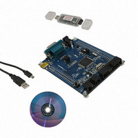
KIT EVAUATION NUC100/120/130/140
Manufacturer
Nuvoton Technology Corporation of America
Series
NuMicro™r
Type
MCUr
Datasheets
1.NUC100LC1BN.pdf
(600 pages)
2.NUMICRO-SDK.pdf
(13 pages)
3.NUMICRO-SDK.pdf
(93 pages)
4.NUMICRO-SDK.pdf
(1 pages)
Specifications of NUMICRO-SDK
Contents
Board, Cable, CD, Nu-Link
Lead Free Status / RoHS Status
Lead free / RoHS Compliant
For Use With/related Products
NUC100, NUC120, NUC130, NUC140
Available stocks
Company
Part Number
Manufacturer
Quantity
Price
Company:

Part Number:
NUMICRO-SDK
Manufacturer:
Nuvoton Technology Corporation
Quantity:
135
Company:
Part Number:
NUMICRO-SDK
Manufacturer:
NuvoTon
Quantity:
69


5.10.4 Function Description
5.10.4.1 One –Shot mode
5.10.4.2 Periodic mode
5.10.4.3 Toggle mode
Timer controller provides one-shot, period and toggle modes operation. Each operating function
mode is shown as following:
If timer is operated at one-shot mode and CEN (timer enable bit) is set to 1, the timer counter
starts up counting. Once the timer counter value reaches timer compare register (TCMPR) value,
if IE (interrupt enable bit) is set to 1’b1, then the timer interrupt flag is set and the interrupt signal
is generated and sent to NVIC to inform CPU. It indicates that the timer counting overflow
happens. If IE (interrupt enable bit) is set to 0, no interrupt signal is generated. In this operating
mode, once the timer counter value reaches timer compare register (TCMPR) value, the timer
counter value goes back to counting initial value and CEN (timer enable bit) is cleared to 0 by
timer controller. Timer counting operation stops, once the timer counter value reaches timer
compare register (TCMPR) value. That is to say, timer operates timer counting and compares
with TCMPR value function only one time after programming the timer compare register (TCMPR)
value and CEN (timer enable bit) is set to 1. So, this operating mode is called One-Shot mode.
If timer is operated at period mode and CEN (timer enable bit) is set to 1, the timer counter starts
up counting. Once the timer counter value reaches timer compare register (TCMPR) value, if IE
(interrupt enable bit) is set to 1’b1, then the timer interrupt flag is set and the interrupt signal is
generated and sent to NVIC to inform CPU. It indicates that the timer counting overflow happens.
If IE (interrupt enable bit) is set to 0, no interrupt signal is generated. In this operating mode, once
the timer counter value reaches timer compare register (TCMPR) value, the timer counter value
goes back to counting initial value and CEN is kept at 1 (counting enable continuously). The timer
counter operates up counting again. If the interrupt flag is cleared by software, once the timer
counter value reaches timer compare register (TCMPR) value and IE (interrupt enable bit) is set
to 1’b1, then the timer interrupt flag is set and the interrupt signal is generated and sent to NVIC
to inform CPU again. That is to say, timer operates timer counting and compares with TCMPR
value function periodically. The timer counting operation doesn’t stop until the CEN is set to 0.
The interrupt signal is also generated periodically. So, this operating mode is called Periodic
mode.
If timer is operated at toggle mode and CEN (timer enable bit) is set to 1, the timer counter starts
up counting. Once the timer counter value reaches timer compare register (TCMPR) value, if IE
(interrupt enable bit) is set to 1’b1, then the timer interrupt flag is set and the interrupt signal is
generated and sent to NVIC to inform CPU. It indicates that the timer counting overflow happens.
The associated toggle output (tout) signal is set to 1. In this operating mode, once the timer
counter value reaches timer compare register (TCMPR) value, the timer counter value goes back
to counting initial value and CEN is kept at 1 (counting enable continuously). The timer counter
operates up counting again. If the interrupt flag is cleared by software, once the timer counter
value reaches timer compare register (TCMPR) value and IE (interrupt enable bit) is set to 1, then
the timer interrupt flag is set and the interrupt signal is generated and sent to NVIC to inform CPU
again. The associated toggle output (tout) signal is set to 0. The timer counting operation doesn’t
stop until the CEN is set to 0. Thus, the toggle output (tout) signal is changing back and forth with
50% duty cycle. So, this operating mode is called Toggle mode.
NuMicro™ NUC100 Series Technical Reference Manual
- 368 -
Publication Release Date: Dec. 22, 2010
Revision V1.06
Related parts for NUMICRO-SDK
Image
Part Number
Description
Manufacturer
Datasheet
Request
R

Part Number:
Description:
IC MCU 32BIT 32KB FLASH 33QFN
Manufacturer:
Nuvoton Technology Corporation of America
Datasheet:
Part Number:
Description:
IC MCU 32BIT 32KB FLASH 48LQFP
Manufacturer:
Nuvoton Technology Corporation of America
Datasheet:

Part Number:
Description:
IC MCU 32BIT 32KB FLASH 48LQFP
Manufacturer:
Nuvoton Technology Corporation of America
Datasheet:

Part Number:
Description:
IC MCU 32BIT 64KB FLASH 33QFN
Manufacturer:
Nuvoton Technology Corporation of America
Datasheet:

Part Number:
Description:
IC MCU 32BIT 32KB FLASH 48LQFP
Manufacturer:
Nuvoton Technology Corporation of America
Datasheet:

Part Number:
Description:
IC MCU 32BIT 64KB FLASH 48LQFP
Manufacturer:
Nuvoton Technology Corporation of America
Datasheet:

Part Number:
Description:
IC MCU 32BIT 64KB FLASH 64LQFP
Manufacturer:
Nuvoton Technology Corporation of America
Datasheet:

Part Number:
Description:
IC MCU 32BIT 64KB FLASH 64LQFP
Manufacturer:
Nuvoton Technology Corporation of America
Datasheet:

Part Number:
Description:
IC MCU 32BIT 64KB FLASH 48LQFP
Manufacturer:
Nuvoton Technology Corporation of America
Datasheet:
Part Number:
Description:
IC MCU 32BIT 64KB FLASH 64LQFP
Manufacturer:
Nuvoton Technology Corporation of America
Datasheet:

Part Number:
Description:
IC MCU 32BIT 8KB FLASH 33QFN
Manufacturer:
Nuvoton Technology Corporation of America
Datasheet:

Part Number:
Description:
IC MCU 32BIT 8KB FLASH 48LQFP
Manufacturer:
Nuvoton Technology Corporation of America
Datasheet:
Part Number:
Description:
IC MCU 32BIT 16KB FLASH 33QFN
Manufacturer:
Nuvoton Technology Corporation of America
Datasheet:
Part Number:
Description:
IC MCU 32BIT 64KB FLASH 100LQFP
Manufacturer:
Nuvoton Technology Corporation of America
Datasheet:

Part Number:
Description:
IC MCU 32BIT 128KB FLASH 64LQFP
Manufacturer:
Nuvoton Technology Corporation of America
Datasheet: