GCM1555C1H221JA16D Murata, GCM1555C1H221JA16D Datasheet - Page 19
GCM1555C1H221JA16D
Manufacturer Part Number
GCM1555C1H221JA16D
Description
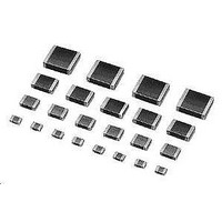
Multilayer Ceramic Capacitors (MLCC) - SMD/SMT 0402 220pF 50volts C0G +/-5%
Manufacturer
Murata
Series
GCMr
Datasheets
1.GCM188R71C105KA64D.pdf
(50 pages)
2.GCM1555C1H221JA16D.pdf
(2 pages)
3.GCM1555C1H221JA16D.pdf
(1 pages)
Specifications of GCM1555C1H221JA16D
Voltage Rating
50 Volts
Operating Temperature Range
- 55 C to + 125 C
Temperature Coefficient / Code
C0G (NP0)
Product
Automotive MLCCs
Dimensions
0.5 mm W x 1 mm L x 0.5 mm H
Dissipation Factor Df
0.01
Termination Style
SMD/SMT
Capacitance
220 pF
Tolerance
5 %
Package / Case
0402 (1005 metric)
Lead Free Status / RoHS Status
Lead free / RoHS Compliant
Available stocks
Company
Part Number
Manufacturer
Quantity
Price
Company:

Part Number:
GCM1555C1H221JA16D
Manufacturer:
MURATA
Quantity:
640 000


!Note
• This PDF catalog is downloaded from the website of Murata Manufacturing co., ltd. Therefore, it’s specifications are subject to change or our products in it may be discontinued without advance notice. Please check with our
• This PDF catalog has only typical specifications because there is no space for detailed specifications. Therefore, please approve our product specifications or transact the approval sheet for product specifications before ordering.
sales representatives or product engineers before ordering.
!Note
*1: The figure indicates typical inspection. Please refer to individual specifications.
*2: Some of the parts are applicable in rated voltage x 150%. Please refer to individual specifications.
Table A
No.
21
Note 1: Nominal values denote the temperature coefficient within a range of 25°C to 125°C (for 5C).
GCM Series Specification and Test Methods
Continued from the preceding page.
Capacitance
Temperature
Character-
istics
Char.
• Please read rating and !CAUTION (for storage, operating, rating, soldering, mounting and handling) in this catalog to prevent smoking and/or burning, etc.
• This catalog has only typical specifications because there is no space for detailed specifications. Therefore, please approve our product specifications or transact the approval sheet for product specifications before ordering.
5C
AEC-Q200
Test Item
Capacitance
Change
Temperature
Coefficient
Capacitance
Drift
Nominal Values (ppm/°C) Note1
Temperature Compensating Type
Within the specified tolerance
(Table A)
Within the specified tolerance
(Table A)
Within ±0.2% or ±0.05 pF
(Whichever is larger)
* Do not apply to 1X/25V
0T30
Specifications
Max.
0.58
C7: Within ±22%
(-55°C to +125°C)
R7: Within ±15%
(-55°C to +125°C)
High Dielectric Type
-55
-0.24
Min.
Capacitance Change from 25°C (%)
The capacitance change should be measured after 5 min. at
each specified temperature stage.
(1) Temperature Compensating Type
(2) High Dielectric Constant Type
Specifications and Test Methods
Max.
0.40
The temperature coefficient is determined using the capacitance
measured in step 3 as a reference. When cycling the
temperature sequentially from step1 through 5 (∆C: +25°C to
+125°C: other temp. coeffs.: +25°C to +85°C) the capacitance
should be within the specified tolerance for the temperature
coefficient and capacitance change as shown in Table A. The
capacitance drift is calculated by dividing the differences
between the maximum and minimum measured values in steps
1, 3 and 5 by the capacitance value in step 3.
The ranges of capacitance change compared with the above
25°C value over the temperature ranges shown in the table
should be within the specified ranges.
· Initial measurement for high dielectric constant type.
Perform a heat treatment at 150+0/-10°C for one hour and then
set for 24±2 hours at room temperature.
Perform the initial measurement.
Step
1
2
3
4
5
-30
-0.17
Min.
AEC-Q200 Test Method
Temperature (°C)
125±3
-55±3
25±2
25±2
25±2
Max.
0.25
-10
-0.11
Min.
C03E.pdf
17
09.3.31
1
Related parts for GCM1555C1H221JA16D
Image
Part Number
Description
Manufacturer
Datasheet
Request
R

Part Number:
Description:
Murata Microblower 20x20 DCDC Driver Board - Samples Only
Manufacturer:
Murata
Part Number:
Description:
357-036-542-201 CARDEDGE 36POS DL .156 BLK LOPRO
Manufacturer:
Murata
Datasheet:
Part Number:
Description:
Manufacturer:
Murata
Datasheet:
Part Number:
Description:
Manufacturer:
Murata
Datasheet:
Part Number:
Description:
Manufacturer:
Murata
Datasheet:
Part Number:
Description:
Manufacturer:
Murata
Datasheet:
Part Number:
Description:
Manufacturer:
Murata
Datasheet:
Part Number:
Description:
Manufacturer:
Murata
Datasheet:
Part Number:
Description:
Manufacturer:
Murata
Datasheet:
Part Number:
Description:
BLM21BD751SN1On-Board Type (DC) EMI Suppression Filters
Manufacturer:
Murata
Datasheet:
Part Number:
Description:
BLM15AG100SN1On-Board Type (DC) EMI Suppression Filters
Manufacturer:
Murata
Datasheet:
Part Number:
Description:
NFE31PT222Z1E9On-Board Type (DC) EMI Suppression Filters
Manufacturer:
Murata
Datasheet:
Part Number:
Description:
Chip Coil
Manufacturer:
Murata
Datasheet:
Part Number:
Description:
Chip Coil
Manufacturer:
Murata
Datasheet: