GCM1555C1H221JA16D Murata, GCM1555C1H221JA16D Datasheet - Page 23
GCM1555C1H221JA16D
Manufacturer Part Number
GCM1555C1H221JA16D
Description
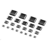
Multilayer Ceramic Capacitors (MLCC) - SMD/SMT 0402 220pF 50volts C0G +/-5%
Manufacturer
Murata
Series
GCMr
Datasheets
1.GCM188R71C105KA64D.pdf
(50 pages)
2.GCM1555C1H221JA16D.pdf
(2 pages)
3.GCM1555C1H221JA16D.pdf
(1 pages)
Specifications of GCM1555C1H221JA16D
Voltage Rating
50 Volts
Operating Temperature Range
- 55 C to + 125 C
Temperature Coefficient / Code
C0G (NP0)
Product
Automotive MLCCs
Dimensions
0.5 mm W x 1 mm L x 0.5 mm H
Dissipation Factor Df
0.01
Termination Style
SMD/SMT
Capacitance
220 pF
Tolerance
5 %
Package / Case
0402 (1005 metric)
Lead Free Status / RoHS Status
Lead free / RoHS Compliant
Available stocks
Company
Part Number
Manufacturer
Quantity
Price
Company:

Part Number:
GCM1555C1H221JA16D
Manufacturer:
MURATA
Quantity:
640 000


!Note
• This PDF catalog is downloaded from the website of Murata Manufacturing co., ltd. Therefore, it’s specifications are subject to change or our products in it may be discontinued without advance notice. Please check with our
• This PDF catalog has only typical specifications because there is no space for detailed specifications. Therefore, please approve our product specifications or transact the approval sheet for product specifications before ordering.
sales representatives or product engineers before ordering.
!Note
Chip monolithic ceramic capacitors (chips) can
experience degradation of termination solderability
when subjected to high temperature or humidity, or if
exposed to sulfur or chlorine gases.
Storage environment must be at an ambient temperature
of 5-40 degree C and an ambient humidity of 20-70%RH.
Use chip within 6 months. If 6 months or more have
elapsed, check solderability before use.
Insulation Resistance should be deteriorated on specific
condition of high humidity or incorrosion gas such as
hydrogen sulfide, sulfurous acid gas, chlorine. Those
condition are not suitable for use.
1. Inspection
2. Board Separation (or depanalization)
(1) Board flexing at the time of separation causes
(2) Severity of stresses imposed on the chip at the
(3) Board separation must be performed using special
!Caution (Storage and Operating Condition)
!Caution (Handling)
Thrusting force of the test probe can flex the PCB,
resulting in cracked chips or open solder joints.
Provide support pins on the back side of the PCB to
prevent warping or flexing.
cracked chips or broken solder.
time of board break is in the order of:
Pushback<Slitter<V Slot<Perforator.
jigs, not with hands.
• Please read rating and !CAUTION (for storage, operating, rating, soldering, mounting and handling) in this catalog to prevent smoking and/or burning, etc.
• This catalog has only typical specifications because there is no space for detailed specifications. Therefore, please approve our product specifications or transact the approval sheet for product specifications before ordering.
Use of Sn-Zn based solder will deteriorate
reliability of MLCC.
Please contact murata factory for the use of Sn-Zn
based solder in advance.
Do not use under the condition that causes
condensation. Use dampproof countermeasure if using
under the condition that causes condensation.
FAILURE TO FOLLOW THE ABOVE CAUTIONS MAY
RESULT, WORST CASE, IN A SHORT CIRCUIT
AND CAUSE FUMING OR PARTIAL DISPERSION
WHEN THE PRODUCT IS USED.
3. Reel and bulk case
FAILURE TO FOLLOW THE ABOVE CAUTIONS MAY
RESULT, WORST CASE, IN A SHORT CIRCUIT
AND FUMING WHEN THE PRODUCTS IS USED.
In the handling of reel and case, please be careful
and do not drop it.
Do not use chips from a case which has been dropped.
!Caution
C03E.pdf
21
09.3.31
1
Related parts for GCM1555C1H221JA16D
Image
Part Number
Description
Manufacturer
Datasheet
Request
R

Part Number:
Description:
Murata Microblower 20x20 DCDC Driver Board - Samples Only
Manufacturer:
Murata
Part Number:
Description:
357-036-542-201 CARDEDGE 36POS DL .156 BLK LOPRO
Manufacturer:
Murata
Datasheet:
Part Number:
Description:
Manufacturer:
Murata
Datasheet:
Part Number:
Description:
Manufacturer:
Murata
Datasheet:
Part Number:
Description:
Manufacturer:
Murata
Datasheet:
Part Number:
Description:
Manufacturer:
Murata
Datasheet:
Part Number:
Description:
Manufacturer:
Murata
Datasheet:
Part Number:
Description:
Manufacturer:
Murata
Datasheet:
Part Number:
Description:
Manufacturer:
Murata
Datasheet:
Part Number:
Description:
BLM21BD751SN1On-Board Type (DC) EMI Suppression Filters
Manufacturer:
Murata
Datasheet:
Part Number:
Description:
BLM15AG100SN1On-Board Type (DC) EMI Suppression Filters
Manufacturer:
Murata
Datasheet:
Part Number:
Description:
NFE31PT222Z1E9On-Board Type (DC) EMI Suppression Filters
Manufacturer:
Murata
Datasheet:
Part Number:
Description:
Chip Coil
Manufacturer:
Murata
Datasheet:
Part Number:
Description:
Chip Coil
Manufacturer:
Murata
Datasheet: