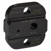
220189-3 Tyco Electronics, 220189-3 Datasheet - Page 4

220189-3
Manufacturer Part Number
220189-3
Description
Crimp Tool Die
Manufacturer
Tyco Electronics
Series
PRO-CRIMPER IIr
Type
Dier
Datasheet
1.220189-1.pdf
(5 pages)
Specifications of 220189-3
Features
"O" / Military
Crimp Application
Coaxial
Connector Type
BNC
Crimp Handle
A9996-ND
Crimp Or Cable Size
RG/U-55, 58, 141, 142, 223, 303, 400, Belden 88240
Product
Tool Component
Description/function
O Military Type
Fits Cable/wire
55, 55A, 55B, 58, 58A, 58B, 58C, 141, 141A, 142, 142A, 142B, 223, 303, 400, Belden 88240, Berk-Tek BTDC-58, Comm/Scope 2135
For Use With
50 Ohm BNC RF/Coaxial Connectors
Lead Free Status / RoHS Status
na
Lead Free Status / RoHS Status
na, Not applicable / Not applicable
Other names
A24777
If the crimping chambers conform to the gage
inspection, the dies are considered dimensionally
correct and should be lubricated with a thin coat of
any good SAE 20 motor oil. If not, the dies must be
replaced before returning them to service.
For additional information concerning the use of the
plug gage, refer to Instruction Sheet 408--7424.
4 of 5
DIE ASSEMBLY
DIE ASSEMBLY
GO
Dia
2. Align the GO element of the gage with the
crimping chamber. Push the element straight into
the chamber without using force. The GO element
must pass completely through the crimping
chamber as shown in Figure 5.
3. Align the NO--GO element with the crimping
chamber and try to insert it straight into the
chamber. The NO--GO element may start entry but
must not pass completely through. See Figure 5.
PART NO.
220189--1
220189--2
220189--3
58330--1
Suggested Plug Gage Design for
Center Contact Crimping Chamber
[.0475--.0478]
[.0415--.0418]
[.0758--.0759]
[.0405--.0408]
1.207--1.214
1.054--1.062
1.925--1.928
1.029--1.036
GO Element
GO
CENTER CONTACT
Crimping
Chamber
[.0535--.0538]
[.0465--.0468]
[.0781--.0782]
[.0465--.0468]
1.359--1.367
1.181--1.189
1.984--1.986
1.181--1.189
NO- - GO
NO- - GO
Dia
GAGE ELEMENT DIAMETER (mm [in.])
Figure 5
[.2030--.2033]
[.2128--.2129]
[.1650--.1653]
[.2350--.2353
CRIMPING CHAMBER
5.156--5.164
5.969--5.977
5.405--5.408
4.191--4.199
7. REPLACEMENT
Parts listed in Figure 6 are customer--replaceable. A
complete inventory can be stocked and controlled to
prevent lost time when replacement of parts is neces-
sary. Order replacements through your local TE
Representative, or call 1--800--526--5142, or send a
facsimile of your purchase order to 1--717--986--7605,
or write to:
8. REVISION SUMMARY
GO
NO- - GO Element
CUSTOMER SERVICE (38--35)
TYCO ELECTRONICS CORPORATION
P.O. BOX 3608
HARRISBURG, PA 17105--3608
GO
Dia
S
Updated document to corporate requirements.
Suggested Plug Gage Design
for Ferrule Crimping Chamber
[.2129--.2130]
[.2449--.2450]
[.2231--.2232]
[.1749--.1750]
5.408--5.410
6.220--6.223
5.667--5.669
4.442--4.445
NO- - GO
“GO” element must
pass completely through
the die closure.
“NO- - GO” element may enter
partially, but must not pass
completely through the die closure.
FERRULE
‘‘R” (Max)
RADIUS
[.099]
[.104]
[.080]
[.115]
2.51
2.92
2.64
2.03
NO- - GO
Dia
‘‘W” (Max)
W
WIDTH
408- 2786
[.198]
[.230]
[.208]
[.160]
5.03
5.84
5.28
4.06
Rev J
R


