58628-2 Tyco Electronics, 58628-2 Datasheet - Page 3
58628-2
Manufacturer Part Number
58628-2
Description
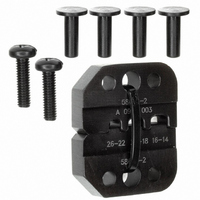
PROCRMP DIESET 26-14 ULTRAFAST
Manufacturer
Tyco Electronics
Series
Pro-Crimper™ IIIr
Type
Crimpersr
Datasheet
1.58628-1.pdf
(4 pages)
Specifications of 58628-2
Rohs Compliant
NA
Connector Type
Terminals and Splices
Crimp Handle
A9996-ND
Crimp Or Cable Size
14-26 AWG
Product
Crimping, Stripping & Cutting Tools & Drills
Fits Cable/wire
26-14 AWG
Lead Free Status / RoHS Status
Not applicable / Not applicable
Lead Free Status / RoHS Status
Not applicable / Not applicable
Other names
A9796


5. CRIMP HEIGHT INSPECTION
This inspection requires the use of a plug gage
conforming to the dimensions provided in Figure 4.
Tyco Electronics does not manufacture or market
these gages. To gage the crimping chambers,
proceed as follows:
If the crimping chambers conform to the gage
inspection, they are considered dimensionally correct,
and should be lubricated with a THIN coat of any
Rev A
Crimping
Chamber
6. Inspect the crimped receptacle to ensure that
the crimp is centered on the wire barrel and the
wire is fully inserted. Check the receptacle crimp
height as described in Section 5. If necessary,
adjust the crimp height as described in Section 6.
NOTE
1. Remove traces of oil or dirt from crimping
chambers and plug gages.
2. Close the tool handles until it is evident that the
dies have bottomed; hold the tool in this position.
Do NOT force the dies beyond initial contact.
3. Carefully insert GO element straight into the
corresponding crimping chamber; do not force it.
The GO element must pass completely through the
crimping chamber. See Figure 4.
4. In the same manner, try to insert the NO--GO
element into the same crimping chamber. The
NO--GO element may start entry, but must not
pass completely through the crimping chamber.
i
Refer to 408- - 7424 for information about the use
and ordering of plug gages and crimp- - height
comparators.
Tyco Electronics Corporation
Back of Tool
Receptacle
Figure 3
good SAE 20 motor oil. If not, the tool must be
adjusted according to Section 6, CRIMP HEIGHT
ADJUSTMENT.
GO Dim.
Crimping
Crimping
Chamber
26--22
22--18
16--14
GO
Element
Suggested Plug Gage Design
Crimping
Chamber
Gage Element Dimensions (mm [in.])
1.4732--1.4808
1.6002--1.6078
1.8542--1.8618
[.0580--.0583]
[.0630--.0633]
[.0730--.0733]
25.4 [1.00]
Min Typ
Figure 4
GO
Crimper Die
Anvil Die
NO- - GO
Element
1.5723--1.5748
1.6993--1.7018
1.9532--1.9558
[.0619--.0620]
[.0669--.0670]
[.0769--.0770]
NO- - GO Dim.
NO- - GO
Strip Length
Wire
3 of 4