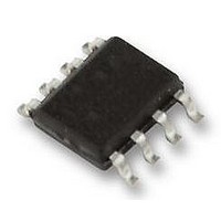
IC-WKL SO8 LASER COMPONENTS, IC-WKL SO8 Datasheet - Page 6

IC-WKL SO8
Manufacturer Part Number
IC-WKL SO8
Description
IC, DRIVER LASER DIODE, SOIC8, WKL
Manufacturer
LASER COMPONENTS
Datasheet
1.IC-WKL_SO8.pdf
(8 pages)
Specifications of IC-WKL SO8
Laser Driver Type
Laser Diode
Supply Current
90mA
Supply Voltage Range
2.4V To 6V
Driver Case Style
SOIC
No. Of Pins
8
Operating Temperature Max
85°C
Operating Temperature Min
-40°C
Package
RoHS Compliant
Base Number
08
Device Type
LED
Ic Generic Number
WKL
Rohs Compliant
Yes
Laser light can damage the human eye and the
eyes of animals! Do not look at any laser light di-
rectly or through any optical lens. When handling a
laser diode, do not look directly at the light generated
by it. Wear appropriate safety glasses to prevent light
from entering the eye even by reflection.
Turn-on behaviour
After switching on the supply voltage the output stage
remains disabled until the internal enabling flip-flop is
set by a sufficiently high voltage at LDA.
A quick soft start occurs during phase I; the control
capacitor CI is loaded at an accelerated rate until the
output stage supplies current at LDK. An open-circuit
voltage at pin MDA is used to verify the external resis-
tance.
Phase II, the initialisation process, begins when cur-
rent starts to flow at LDK. This phase ends when the
laser reaches its threshold current and the monitor cur-
rent produced raises the potential at resistor RM.
The transition to CW operation (phase III) is gradual
and primarily influenced by the CI and RM compo-
nents. CI is properly dimensioned when the voltage
overshot at MDA is at a minimum.
Turn-off behaviour
iC-WK/L functions without a fixed undervoltage lock-
SAFETY INSTRUCTIONS
TURN-ON/OFF BEHAVIOUR
iC-WK, iC-WKL
2.4 V CW LASER DIODE DRIVER
200 uA
60 mA
0.6V
2.0 V
0 mA
5.0 V
5.0 V
0 uA
0 V
0 V
0 V
0 V
0 s
−I(MDA)
V(MDA)
V(CI)
I(LDK)
V(LDA)
Figure 1: Turn-on behaviour
V(VCC)
10 us
Phase I
20 us
Phase II
30 us
40 us
Phase III
t
50 us
out, thus the laser diode forward voltage is the prime
factor determining the lowest possible supply voltage.
If the voltage drops below this, the output stage is
forcibly saturated and the laser current falls. In this in-
stance iC-WK/L simultaneously discharges control ca-
pacitor CI so that no excessive laser diode currents
occur when the supply voltage rises again.
Disruptions in operation
The power control is shut down with excessive driver
temperature or when the laser current reaches the
overcurrent shutdown threshold, for example when the
feedback is interrupted. If the monitor diode or the pre-
set resistor RM fail, the device is shutdown in less than
250 µs, provided that the supply voltage applied is high
enough.
When modulating or switching the laser current via pin
MDK (see Application Notes), excessive Voltage oc-
curring at pin MDA also causes a shut down (iC-WK
only).
200 uA
60 mA
0.6 V
5.0 V
2.0 V
0 mA
5.0 V
0 uA
0 V
0 V
0 V
0 V
100 us
V(VCC)
V(LDA)
−I(MDA)
V(MDA)
V(CI)
I(LDK)
Figure 2: Turn-off behaviour
Phase IV
150 us
Phase V
200 us
250 us
Rev D1, Page 6/8
t
300 us


