HT82K629A-40DIPLF HOLTEK, HT82K629A-40DIPLF Datasheet - Page 21
HT82K629A-40DIPLF
Manufacturer Part Number
HT82K629A-40DIPLF
Description
IC, USB/PS2 CONT, WIN 2000 KEYBOARD
Manufacturer
HOLTEK
Datasheet
1.HT82K629A-40DIPLF.pdf
(23 pages)
Specifications of HT82K629A-40DIPLF
Usb Type
Keyboard Encoder
Usb Version
1.1
Supply Voltage Range
4.4V To 5.5V
Operating Temperature Range
0°C To +70°C
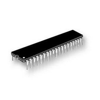
Digital Ic Case Style
DIP
No. Of Pins
40
Operating Temperature Max
70°C
Base Number
82
Rohs Compliant
Yes
Lead Free Status / RoHS Status
Lead free / RoHS Compliant


Application Circuits
Note:
Rev. 1.40
For single side PCB, the GND should be routed first. Avoid routing the GND line and VDD line with jumping
wires.
The GND and VDD lines should be as wide as possible, also it is recommended that the GND and VDD lines
are placed in an empty area, in order to increase their area. Wherever possible the GND plane should surround
pins such as OSCI, OSCO, VDD, V330, RESET etc and other related circuits to minimize the noise effects.
The GND/VDD loop area should be minimized. Try to keep GND and VDD lines parallel.
The external 22 resistor and 0.01 F capacitor connected to the VDD pin should be placed as close as possi-
ble to the VDD pin.
Allow room in the layout for the 0.1 F capacitor that is connected to the VDD pin. This capacitor should be con-
nected as close as possible to the VDD pin. The function of this capacitor is to filter out high frequency noise.
The lines connecting the OSCI and OSCO pins to the crystal must be kept as short as possible to minimize any
cross coupling of noise from these pins.
The 0.1 F capacitor connected to the RESET pin should be placed as close as possible to the RESET pin. The
function of this capacitor is to filter out high frequency noise to minimize the possibility of a glitch on this line
causing a false reset.
The 0.1 F capacitor connected to the V33O pin should be placed as close as possible to the V33O pin.
The USBD+ and USBD- lines to the USB connector should be kept as short as possible and should not be
placed close to the other lines to reduce the possibility of noise coupling into other lines. The externally con-
nected 1.5k resistor connected to the USBD- pin should be placed as close to as possible the USBD- pin.
The USB cable should preferably have proper shielding.
21
September 15, 2004
HT82K629A
Related parts for HT82K629A-40DIPLF
Image
Part Number
Description
Manufacturer
Datasheet
Request
R

Part Number:
Description:
DTMF receiver
Manufacturer:
Holtek
Datasheet:
Part Number:
Description:
RAM mapping 32x4 LCD controller for I/O uC
Manufacturer:
Holtek
Datasheet:
Part Number:
Description:
3 in 12 decoder. 8-addresses, 4-data
Manufacturer:
Holtek
Datasheet:
Part Number:
Description:
8-Bit I/O Type MCU
Manufacturer:
Holtek
Datasheet:
Part Number:
Description:
1-memory/2-memory tone/pulse dialer
Manufacturer:
Holtek
Datasheet:
Part Number:
Description:
1-memory/2-memory tone/pulse dialer
Manufacturer:
Holtek
Datasheet:
Part Number:
Description:
12-Memory Tone/Pulse Dialer
Manufacturer:
Holtek
Datasheet:
Part Number:
Description:
Single Sound Generator
Manufacturer:
Holtek
Datasheet:
Part Number:
Description:
HT2812DSingle Sound Generator
Manufacturer:
Holtek
Datasheet:
Part Number:
Description:
4-Sound Generator
Manufacturer:
Holtek
Datasheet:
Part Number:
Description:
8-Bit I/O Type MCU
Manufacturer:
Holtek
Datasheet:
Part Number:
Description:
Decoders for burglar alarm system, car door controllers and etc.
Manufacturer:
Holtek
Datasheet:
Part Number:
Description:
8-Bit A/D Type MCU HT46R228-Bit A/D Type MCU
Manufacturer:
Holtek
Datasheet: