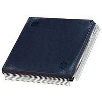
EPM7256AEQC208-7N Altera, EPM7256AEQC208-7N Datasheet - Page 20

EPM7256AEQC208-7N
Manufacturer Part Number
EPM7256AEQC208-7N
Description
IC PLD EEPROM 256 MACROCELL 7.5NS QFP208
Manufacturer
Altera
Series
MAX 7000AEr
Datasheet
1.EPM7032AELC44-10N.pdf
(64 pages)
Specifications of EPM7256AEQC208-7N
Cpld Type
EEPROM
No. Of Macrocells
256
No. Of I/o's
164
Propagation Delay
7.5ns
Global Clock Setup Time
3.9ns
Frequency
172.4MHz
Supply Voltage Range
3V To 3.6V
Lead Free Status / RoHS Status
Lead free / RoHS Compliant
Available stocks
Company
Part Number
Manufacturer
Quantity
Price
Company:
Part Number:
EPM7256AEQC208-7N
Manufacturer:
ALTERA
Quantity:
25
Part Number:
EPM7256AEQC208-7N
Manufacturer:
ALTERA/阿尔特拉
Quantity:
20 000
MAX 7000A Programmable Logic Device Data Sheet
Note to tables:
(1)
Programming
with External
Hardware
IEEE Std.
1149.1 (JTAG)
Boundary-Scan
Support
20
EPM7128A
EPM7256A
Table 7. MAX 7000A Stand-Alone Verification Times for Different Test Clock Frequencies
EPM7032AE
EPM7064AE
EPM7128AE
EPM7256AE
EPM7512AE
EPM7128A and EPM7256A devices can only be programmed with an adaptive algorithm; users programming these
two devices on platforms that cannot use an adaptive algorithm should use EPM7128AE and EPM7256AE devices.
Device
(1)
(1)
f
f
10 MHz
0.00
0.01
0.01
0.02
0.03
0.08
0.13
MAX 7000A devices can be programmed on Windows-based PCs with an
Altera Logic Programmer card, the MPU, and the appropriate device
adapter. The MPU performs continuity checks to ensure adequate
electrical contact between the adapter and the device.
For more information, see the
The Altera software can use text- or waveform-format test vectors created
with the Altera Text Editor or Waveform Editor to test the programmed
device. For added design verification, designers can perform functional
testing to compare the functional device behavior with the results of
simulation.
Data I/O, BP Microsystems, and other programming hardware
manufacturers provide programming support for Altera devices.
For more information, see
MAX 7000A devices include the JTAG BST circuitry defined by IEEE Std.
1149.1.
devices. The pin-out tables, available from the Altera web site
(http://www.altera.com), show the location of the JTAG control pins for
each device. If the JTAG interface is not required, the JTAG pins are
available as user I/O pins.
5 MHz
0.01
0.01
0.02
0.03
0.06
0.14
0.24
Table 8
2 MHz
0.01
0.02
0.04
0.08
0.15
0.29
0.54
describes the JTAG instructions supported by MAX 7000A
1 MHz
0.02
0.04
0.07
0.15
0.30
0.56
1.06
f
Programming Hardware
TCK
500 kHz
0.04
0.07
0.14
0.30
0.60
1.09
2.08
Altera Programming Hardware Data Sheet.
200 kHz
0.09
0.18
0.34
0.75
1.49
2.67
5.15
100 kHz
10.27
0.18
0.35
0.68
1.49
2.97
5.31
Manufacturers.
Altera Corporation
50 kHz
10.59
20.51
0.36
0.70
1.36
2.98
5.94
Units
s
s
s
s
s
s
s


