74AHCT1G04GW/T1 NXP Semiconductors, 74AHCT1G04GW/T1 Datasheet - Page 2
74AHCT1G04GW/T1
Manufacturer Part Number
74AHCT1G04GW/T1
Description
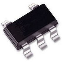
74AHCT SINGLE GATE, SMD, 74AHCT1G04
Manufacturer
NXP Semiconductors
Datasheet
1.74AHCT1G04GWT1.pdf
(16 pages)
Specifications of 74AHCT1G04GW/T1
Output Current
8mA
No. Of Inputs
5
Supply Voltage Range
4.5V To 5.5V
Logic Case Style
SOT-353
No. Of Pins
5
Operating Temperature Range
-40°C To +125°C
Svhc
No SVHC
Logic Type
Inverter Gate
Lead Free Status / RoHS Status
Lead free / RoHS Compliant


Philips Semiconductors
FEATURES
QUICK REFERENCE DATA
GND = 0 V; T
Notes
1. C
2. The condition is V
2003 Sep 04
t
C
C
SYMBOL
PHL
Symmetrical output impedance
High noise immunity
ESD protection:
– HBM EIA/JESD22-A114-A exceeds 2000 V
– MM EIA/JESD22-A115-A exceeds 200 V
– CDM EIA/JESD22-C101 exceeds 1000 V.
Low power dissipation
Balanced propagation delays
Very small 5-pin package
Specified from 40 to +85 C and 40 to +125 C.
I
PD
Inverter
P
f
f
C
V
N = total load switching outputs;
i
o
/t
D
CC
PD
= input frequency in MHz;
L
(C
PLH
= output frequency in MHz;
= output load capacitance in pF;
= C
L
is used to determine the dynamic power dissipation (P
= supply voltage in Volts;
PD
V
propagation delay input A to output Y C
input capacitance
power dissipation capacitance
CC
amb
2
V
CC
= 25 C; t
f
o
2
) = sum of outputs.
I
f
= GND to V
i
PARAMETER
N + (C
r
= t
f
3.0 ns.
CC
L
.
V
CC
2
f
o
) where:
C
notes 1 and 2
L
L
= 15 pF; V
= 50 pF; f = 1 MHz;
CONDITIONS
2
DESCRIPTION
The 74AHC1G04/74AHCT1G04 are high-speed Si-gate
CMOS devices.
The 74AHC1G04/74AHCT1G04 provides the inverting
buffer.
D
in W).
CC
= 5 V
74AHC1G04; 74AHCT1G04
3.1
1.5
15
74AHC1G04
TYPICAL
74AHCT1G04
3.4
1.5
16
Product specification
ns
pF
pF
UNIT
Related parts for 74AHCT1G04GW/T1
Image
Part Number
Description
Manufacturer
Datasheet
Request
R

Part Number:
Description:
IC BUFF/DVR TRI-ST DUAL 20TSSOP
Manufacturer:
NXP Semiconductors
Datasheet:

Part Number:
Description:
IC BUFF DVR TRI-ST QD 14SOICN
Manufacturer:
NXP Semiconductors
Datasheet:

Part Number:
Description:
IC BUFF DVR TRI-ST QD 14TSSOP
Manufacturer:
NXP Semiconductors
Datasheet:

Part Number:
Description:
IC BUFF/DVR TRI-ST DUAL 20SOIC
Manufacturer:
NXP Semiconductors
Datasheet:
Part Number:
Description:
IC TRANSCVR TRI-ST 8BIT 20SOIC
Manufacturer:
NXP Semiconductors
Datasheet:
Part Number:
Description:
IC TRANSCVR TRI-ST 8BIT 20TSSOP
Manufacturer:
NXP Semiconductors
Datasheet:
Part Number:
Description:
IC BUFF/DVR TRI-ST 8BIT 20SOIC
Manufacturer:
NXP Semiconductors
Datasheet:
Part Number:
Description:
IC BUFF/DVR 3-ST QUAD 14-TSSOP
Manufacturer:
NXP Semiconductors
Datasheet:

Part Number:
Description:
IC D F-F POS-EDGE TRIG SC88A-5
Manufacturer:
NXP Semiconductors
Datasheet:

Part Number:
Description:
IC D F-F POS-EDGE TRIG SC74A-5
Manufacturer:
NXP Semiconductors
Datasheet:
Part Number:
Description:
IC DUAL D F-F POS-EDG 14SOIC
Manufacturer:
NXP Semiconductors
Datasheet:
Part Number:
Description:
IC DUAL D F-F POS-EDG 14TSSOP
Manufacturer:
NXP Semiconductors
Datasheet:
Part Number:
Description:
IC OCT D F-F POS-EDG TRIG 20SOIC
Manufacturer:
NXP Semiconductors
Datasheet:
Part Number:
Description:
IC OCT D FF POS-EDG TRIG 20TSSOP
Manufacturer:
NXP Semiconductors
Datasheet:
Part Number:
Description:
IC OCT D FF POS-EDG TRIG 20TSSOP
Manufacturer:
NXP Semiconductors
Datasheet: