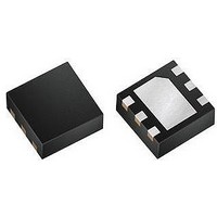
LT3493EDCB#PBF Linear Technology, LT3493EDCB#PBF Datasheet - Page 13

LT3493EDCB#PBF
Manufacturer Part Number
LT3493EDCB#PBF
Description
IC, STEP-DOWN PWM DC/DC CONVERTER, DFN-6
Manufacturer
Linear Technology
Datasheet
1.LT3493EDCBTRMPBF.pdf
(20 pages)
Specifications of LT3493EDCB#PBF
Primary Input Voltage
36V
No. Of Outputs
1
Output Current
1.2A
No. Of Pins
6
Operating Temperature Range
-40°C To +85°C
Supply Voltage Range
3.6V To 36V
Switching Frequency Max
815kHz
Msl
MSL 1 - Unlimited
Rohs Compliant
Yes
Lead Free Status / RoHS Status
Lead free / RoHS Compliant
Available stocks
Company
Part Number
Manufacturer
Quantity
Price
APPLICATIONS INFORMATION
At light loads, the inductor current becomes discontinu-
ous and the effective duty cycle can be very high. This
reduces the minimum input voltage to approximately
400mV above V
current is continuous and the duty cycle is limited by the
maximum duty cycle of the LT3493, requiring a higher
input voltage to maintain regulation.
Soft-Start
The SHDN pin can be used to soft-start the LT3493, reducing
the maximum input current during start-up. The SHDN pin
is driven through an external RC fi lter to create a voltage
ramp at this pin. Figure 7 shows the start-up waveforms
with and without the soft-start circuit. By choosing a large
RC time constant, the peak start-up current can be reduced
to the current that is required to regulate the output, with
no overshoot. Choose the value of the resistor so that it
can supply 20μA when the SHDN pin reaches 2.3V.
Shorted and Reversed Input Protection
If the inductor is chosen so that it won’t saturate exces-
sively, an LT3493 buck regulator will tolerate a shorted
output. There is another situation to consider in systems
(6a) Typical Minimum Input Voltage, V
7.5
7.0
6.5
6.0
5.5
5.0
1
OUT
. At higher load currents, the inductor
TO START
10
TO RUN
I
OUT
(mA)
100
3493 G15
OUT
1000
= 5V
Figure 6
where the output will be held high when the input to the
LT3493 is absent. This may occur in battery charging ap-
plications or in battery backup systems where a battery
or some other supply is diode OR-ed with the LT3493’s
output. If the V
is held high (either by a logic signal or because it is tied
to V
quiescent current through its SW pin. This is fi ne if your
system can tolerate a few mA in this state. If you ground
the SHDN pin, the SW pin current will drop to essentially
zero. However, if the V
is held high, then parasitic diodes inside the LT3493 can
pull large currents from the output through the SW pin
and the V
when the input voltage is present and that protects against
a shorted or reversed input.
Hot Plugging Safely
The small size, robustness and low impedance of ceramic
capacitors make them an attractive option for the input
bypass capacitor of LT3493 circuits. However, these capaci-
tors can cause problems if the LT3493 is plugged into a
live supply (see Linear Technology Application Note 88 for
IN
), then the LT3493’s internal circuitry will pull its
(6b) Typical Minimum Input Voltage, V
IN
5.5
5.3
5.1
4.9
4.7
4.5
4.3
4.1
3.9
3.7
3.5
pin. Figure 8 shows a circuit that will run only
1
IN
pin is allowed to fl oat and the SHDN pin
IN
TO RUN
10
pin is grounded while the output
I
OUT
(mA)
100
TO START
3493 G16
OUT
1000
LT3493
= 3.3V
13
3493fb


