ADIS16400BMLZ Analog Devices Inc, ADIS16400BMLZ Datasheet
ADIS16400BMLZ
Specifications of ADIS16400BMLZ


Related parts for ADIS16400BMLZ


ADIS16400BMLZ Summary of contents
Page 1
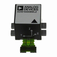
FEATURES Triaxial, digital gyroscope with digital range scaling ±75°/sec, ±150°/sec, ±300°/sec settings Tight orthogonal alighment, <0.05° Triaxial, digital accelerometer, ±18 g Triaxial, digital magnetometer, ±2.5 gauss Autonomous operation and data collection No external configuration commands required 220 ms start-up time ...
Page 2
ADIS16400/ADIS16405 TABLE OF CONTENTS Features .............................................................................................. 1 Applications ....................................................................................... 1 Functional Block Diagram .............................................................. 1 General Description ......................................................................... 1 Revision History ............................................................................... 2 Specifications ..................................................................................... 3 Timing Specifications .................................................................. 6 Timing Diagrams .......................................................................... 6 Absolute Maximum Ratings ............................................................ 7 ESD ...
Page 3
... In-Run Bias Stability Angular Random Walk Bias Temperature Coefficient Linear Acceleration Effect on Bias Bias Voltage Sensitivity Output Noise Rate Noise Density 3 dB Bandwidth ACCELEROMETERS Dynamic Range Initial Sensitivity Sensitivity Temperature Coefficient Misalignment Nonlinearity Initial Bias Error In-Run Bias Stability Velocity Random Walk ...
Page 4
ADIS16400/ADIS16405 Parameter TEMPERATURE SENSOR Scale Factor ADC INPUT Resolution Integral Nonlinearity Differential Nonlinearity Offset Error Gain Error Input Range Input Capacitance DAC OUTPUT Resolution Relative Accuracy Differential Nonlinearity Offset Error Gain Error Output Range Output Impedance Output Settling Time 1 ...
Page 5
Parameter POWER SUPPLY Operating Voltage Range, VCC Power Supply Current 1 The digital I/O signals are driven by an internal 3.3 V supply, and the inputs are 5 V tolerant. 2 Endurance is qualified as per JEDEC Standard 22, Method ...
Page 6
ADIS16400/ADIS16405 TIMING SPECIFICATIONS T = 25°C, VCC = 5 V, unless otherwise noted. A Table 2. Parameter Description f Serial clock frequency SCLK t Stall period between data STALL t Read rate READRATE t Chip select to clock edge CS ...
Page 7
ABSOLUTE MAXIMUM RATINGS Table 3. Parameter Acceleration Any Axis, Unpowered Any Axis, Powered VCC to GND Digital Input Voltage to GND Digital Output Voltage to GND Analog Input to GND Operating Temperature Range Storage Temperature Range 1 Extended exposure to ...
Page 8
ADIS16400/ADIS16405 PIN CONFIGURATION AND FUNCTION DESCRIPTIONS Y-AXIS NOTES Table 5. Pin Function Descriptions Pin No. Mnemonic 1 DIO3 2 DIO4/CLKIN 16, 17, 18, 19, 22, 23, 24 DNC 3 SCLK 4 DOUT 5 DIN ...
Page 9
TYPICAL PERFORMANCE CHARACTERISTICS 0.1 0.01 0.001 0 100 Tau (sec) Figure 7. Gyroscope Root Allan Variance 0.01 +1σ 0.001 MEAN –1σ 0.0001 0.1 1k 10k Rev Page ADIS16400/ADIS16405 +1σ MEAN –1σ ...
Page 10
ADIS16400/ADIS16405 THEORY OF OPERATION BASIC OPERATION The ADIS16400/ADIS16405 are autonomous sensor systems that start up after a valid power supply voltage is applied and then begin producing inertial measurement data at the factory- default sample rate of 819.2 SPS. After ...
Page 11
MEMORY MAP Table 8. User Register Memory Map Name R/W Flash Backup FLASH_CNT R Yes SUPPLY_OUT R No XGYRO_OUT R No YGYRO_OUT R No ZGYRO_OUT R No XACCL_OUT R No YACCL_OUT R No ZACCL_OUT R No XMAGN_OUT R No YMAGN_OUT ...
Page 12
ADIS16400/ADIS16405 CS 1 SCLK DIN 0x3E00 DOUT PREVIOUS OUTPUT DATA REGISTERS Figure 6 provides the positive measurement direction for each gyroscope, accelerometer, and magnetometer. Table 9 provides the configuration and scale factor for each output data register in the ADIS16400/ADIS16405. ...
Page 13
Magnetometer Soft-Iron Correction (Scale Factor) The soft-iron correction factor for the magnetometer provides the opportunity to change the scale factor for each individual axis. Table 13. XMAGN_SIF, YMAGN_SIF, ZMAGN_SIF Bits Description [15:12] Not used. [11:0] Data bits. Binary, linear scale ...
Page 14
ADIS16400/ADIS16405 Digital Filtering A programmable low-pass filter provides additional opportunity for noise reduction on the inertial sensor outputs. This filter contains two cascaded averaging filters that provide a Bartlett window, FIR filter response (see Figure 15). For example, SENS_AVG[2:0] = ...
Page 15
Auxiliary DAC The 12-bit AUX_DAC line can drive its output to within the ground reference when it is not sinking current. As the output approaches 0 V, the linearity begins to degrade (~100 LSB beginning point). As ...
Page 16
ADIS16400/ADIS16405 Alarm Registers The alarm function provides monitoring for two independent conditions. The ALM_CTRL register provides control inputs for data source, data filtering (prior to comparison), static comparison, dynamic rate-of-change comparison, and output indicator configurations. The ALM_MAGx registers establish the ...
Page 17
... Temperature Range 1 ADIS16400BMLZ −40°C to +105° ADIS16400/PCBZ 1 ADIS16405BMLZ −40°C to +105° ADIS16405/PCBZ RoHS Compliant Part. 2 This includes one ADIS16400BMLZ and an interface PCB. 3 This includes one ADIS16405BMLZ and an interface PCB. 9.464 4.20 9.210 4.00 2.382 8.956 3.80 BSC (2×) (2×) 17.41 1 ...
Page 18
ADIS16400/ADIS16405 NOTES Rev Page ...
Page 19
NOTES Rev Page ADIS16400/ADIS16405 ...
Page 20
ADIS16400/ADIS16405 NOTES ©2009 Analog Devices, Inc. All rights reserved. Trademarks and registered trademarks are the property of their respective owners. D07907-0-7/09(B) Rev Page ...