ADIS16400BMLZ Analog Devices Inc, ADIS16400BMLZ Datasheet - Page 6
ADIS16400BMLZ
Manufacturer Part Number
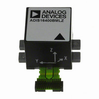
ADIS16400BMLZ
Description
IC, MODULE, GYRO, ACCEL, MAG, 24PIN
Manufacturer
Analog Devices Inc
Datasheet
1.ADIS16400PCBZ.pdf
(20 pages)
Specifications of ADIS16400BMLZ
No. Of Axes
3
No. Of Pins
24
Supply Voltage Range
4.75V To 5.25V
Operating Temperature Range
-40°C To +105°C
Interface
SPI
Acceleration Range
± 18g
Interface Type
SPI
Sensitivity Per Axis
3.33mg / LSB
Sensor Case Style
ML-24-2
Rohs Compliant
Yes
Lead Free Status / RoHS Status
Lead free / RoHS Compliant
For Use With
ADIS16400/PCBZ - BOARD EVAL FOR ADIS16400
Lead Free Status / Rohs Status
Compliant


ADIS16400/ADIS16405
TIMING SPECIFICATIONS
T
Table 2.
Parameter
f
t
t
t
t
t
t
t
t
t
t
t
t
1
TIMING DIAGRAMS
Guaranteed by design and characterization but not tested in production.
SCLK
STALL
READRATE
CS
DAV
DSU
DHD
SCLKR
DF
SFS
1
2
3
A
, t
= 25°C, VCC = 5 V, unless otherwise noted.
DR
, t
SCLKF
DOUT
SCLK
DIN
CS
Description
Serial clock frequency
Stall period between data
Read rate
Chip select to clock edge
DOUT valid after SCLK edge
DIN setup time before SCLK rising edge
DIN hold time after SCLK rising edge
SCLK rise/fall times
DOUT rise/fall times
CS high after SCLK edge
Input sync pulse width
Input sync to data ready output
Input sync period
SCLK
CS
t
CS
1
MSB
W/R
CLOCK (DIO4)
2
READY
A6
SYNC
DATA
DB14
t
DAV
t
DSU
3
A5
t
DB13
1
Figure 4. Input Clock Timing Diagram
Figure 2. SPI Timing and Sequence
Figure 3. Stall Time and Data Rate
4
t
DHD
t
2
Min
0.01
9
40
48.8
24.4
48.8
5
833
t
A4
(SMPL_PRD ≤ 0x09)
READRATE
DB12
Rev. B | Page 6 of 20
t
3
Normal Mode
1
t
5
STALL
Typ
5
5
5
600
A3
DB11
6
Max
2.0
100
12.5
12.5
A2
DB10
Min
0.01
75
150
48.8
24.4
48.8
5
(SMPL_PRD ≥ 0x0A)
Low Power Mode
1
D2
Typ
5
5
DB2
15
Max
0.3
100
12.5
12.5
D1
DB1
16
Min
0.01
1/f
48.8
24.4
48.8
5
833
LSB
LSB
SCLK
1
Burst Mode
t
Typ
5
5
5
600
SFS
Max
1.0
100
12.5
12.5
Unit
MHz
μs
μs
ns
ns
ns
ns
ns
ns
ns
μs
μs
μs
Related parts for ADIS16400BMLZ
Image
Part Number
Description
Manufacturer
Datasheet
Request
R

Part Number:
Description:
±1.7g Dual-Axis IMEMS Accelerometer Evaluation Board
Manufacturer:
Analog Devices Inc
Datasheet:

Part Number:
Description:
Inertial Sensor Evaluation System
Manufacturer:
Analog Devices Inc
Datasheet:
Part Number:
Description:
Manufacturer:
Analog Devices Inc
Datasheet:
Part Number:
Description:
Manufacturer:
Analog Devices Inc
Datasheet:
Part Number:
Description:
Manufacturer:
Analog Devices Inc
Datasheet:
Part Number:
Description:
Manufacturer:
Analog Devices Inc
Datasheet:
Part Number:
Description:
Manufacturer:
Analog Devices Inc
Datasheet:
Part Number:
Description:
Manufacturer:
Analog Devices Inc
Datasheet:
Part Number:
Description:
Manufacturer:
Analog Devices Inc
Datasheet:
Part Number:
Description:
Manufacturer:
Analog Devices Inc
Datasheet:
Part Number:
Description:
Manufacturer:
Analog Devices Inc
Datasheet:
Part Number:
Description:
Manufacturer:
Analog Devices Inc
Datasheet:
Part Number:
Description:
Manufacturer:
Analog Devices Inc
Datasheet: