ATS645LSH-I1 Allegro Microsystems Inc, ATS645LSH-I1 Datasheet - Page 14
ATS645LSH-I1
Manufacturer Part Number
ATS645LSH-I1
Description
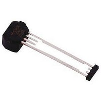
Hall Effect IC
Manufacturer
Allegro Microsystems Inc
Datasheet
1.ATS642LSHTN-I1-T.pdf
(14 pages)
Specifications of ATS645LSH-I1
Termination Type
Through Hole
No. Of Pins
4
Mounting Type
Through Hole
Hall Effect Type
Gear Tooth
Supply Voltage Min
4V
Peak Reflow Compatible (260 C)
No
Bandwidth
40kHz
Output Type
Digital
Filter Terminals
Through Hole
Rohs Compliant
No
Leaded Process Compatible
No
Package / Case
4-SIP
Lead Free Status / RoHS Status
Contains lead / RoHS non-compliant


ATS645LSH
5,581,179; 5,619,137; 5,621,319; 5,650,719; 5,686,894; 5,694,038; 5,729,130; 5,917,320; 6,091,239; 6,100,680; 6,232,768; 6,242,908; 6,265,865;
6,297,627; 6,525,531; 6,690,155; 6,693,419; 6,919,720; 7,046,000; 7,053,674; 7,138,793; 7,199,579; 7,253,614; 7,365,530; 7,368,904; or other
patents pending.
mit improvements in the per for mance, reliability, or manufacturability of its products. Before placing an order, the user is cautioned to verify that the
information being relied upon is current.
failure of that life support device or system, or to affect the safety or effectiveness of that device or system.
nor for any in fringe ment of patents or other rights of third parties which may result from its use.
Copyright ©2004-2009, Allegro MicroSystems, Inc.
The products described herein are manufactured under one or more of the following U.S. patents: 5,264,783; 5,389,889; 5,442,283; 5,517,112;
Allegro MicroSystems, Inc. reserves the right to make, from time to time, such de par tures from the detail spec i fi ca tions as may be required to per-
Allegro’s products are not to be used in life support devices or systems, if a failure of an Allegro product can reasonably be expected to cause the
The in for ma tion in clud ed herein is believed to be ac cu rate and reliable. How ev er, Allegro MicroSystems, Inc. assumes no re spon si bil i ty for its use;
24.65±0.10
13.10±0.10
5.00±0.10
5.80±0.05
4.00±0.10
8.00±0.05
E1
1.70±0.10
A
F
0.75
1
2
5.50±0.10
3
For the latest version of this document, visit our website:
1.27±0.10
True Zero Speed Miniature Differential Peak-
4
0.75
F
0.60±0.10
A
1.00±0.10
1.0 REF
1.60±0.10
E2
Package SH SIP
www.allegromicro.com
Branded
Face
0.71±0.05
0.71±0.10
Detecting Gear Tooth Sensor IC
E
5.50±0.05
0.71±0.10
0.38
B
C
+0.06
–0.04
A
B
C
D
E
F
For Reference Only, not for tooling use (reference DWG-9003)
Dimensions in millimeters
Dambar removal protrusion (16X)
Metallic protrusion, electrically connected to pin 4 and substrate (both sides)
Thermoplastic Molded Lead Bar for alignment during shipment
Branding scale and appearance at supplier discretion
Active Area Depth 0.43 mm REF
Hall elements (E1, E2); not to scale
D
115 Northeast Cutoff
1.508.853.5000; www.allegromicro.com
Allegro MicroSystems, Inc.
Worcester, Massachusetts 01615-0036 U.S.A.
Standard Branding Reference View
W = Week of manufacture
N = Last three numbers of device part number
Y = Last two digits of year of manufacture
L = Lot identifier
= Supplier emblem
LLLLLLL
YYWW
NNN
13
Related parts for ATS645LSH-I1
Image
Part Number
Description
Manufacturer
Datasheet
Request
R

Part Number:
Description:
IC, HALL EFFECT SENSOR, Linear, SOIC-8
Manufacturer:
Allegro Microsystems Inc
Datasheet:
Part Number:
Description:
IC, HALL EFFECT SENSOR, Linear, SOIC-8
Manufacturer:
Allegro Microsystems Inc
Datasheet:
Part Number:
Description:
IC, HALL EFFECT SENSOR, Linear, SOIC-8
Manufacturer:
Allegro Microsystems Inc
Datasheet:

Part Number:
Description:
IC SWITCH INTERFACE 2CHAN 8-SOIC
Manufacturer:
Allegro Microsystems Inc
Datasheet:

Part Number:
Description:
IC SMOKE DETECTOR ION 16-DIP
Manufacturer:
Allegro Microsystems Inc
Datasheet:
Part Number:
Description:
IC SMOKE DETECTOR ION 16-DIP
Manufacturer:
Allegro Microsystems Inc
Datasheet:
Part Number:
Description:
IC SMOKE DETECTOR ION 16-DIP
Manufacturer:
Allegro Microsystems Inc
Datasheet:
Part Number:
Description:
IC SMOKE DETECTOR PHOTO 16-DIP
Manufacturer:
Allegro Microsystems Inc
Datasheet:
Part Number:
Description:
IC SMOKE DETECTOR ION 16-DIP
Manufacturer:
Allegro Microsystems Inc
Datasheet:
Part Number:
Description:
IC SMOKE DETECTOR PHOTO 16-DIP
Manufacturer:
Allegro Microsystems Inc
Datasheet:
Part Number:
Description:
IC SMOKE DETECTOR PHOTO 16-DIP
Manufacturer:
Allegro Microsystems Inc
Datasheet:
Part Number:
Description:
IC SMOKE DETECTOR ION 16-DIP
Manufacturer:
Allegro Microsystems Inc
Datasheet:
Part Number:
Description:
IC SMOKE DETECTOR PHOTO 16-SOIC
Manufacturer:
Allegro Microsystems Inc
Datasheet:

Part Number:
Description:
IC LED DRIVER HIGH BRIGHT 16-QFN
Manufacturer:
Allegro Microsystems Inc
Datasheet:

Part Number:
Description:
IC LED DRIVER AUTOMOTIVE 8-SOIC
Manufacturer:
Allegro Microsystems Inc
Datasheet: