ATS645LSH-I1 Allegro Microsystems Inc, ATS645LSH-I1 Datasheet - Page 6
ATS645LSH-I1
Manufacturer Part Number
ATS645LSH-I1
Description
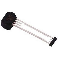
Hall Effect IC
Manufacturer
Allegro Microsystems Inc
Datasheet
1.ATS642LSHTN-I1-T.pdf
(14 pages)
Specifications of ATS645LSH-I1
Termination Type
Through Hole
No. Of Pins
4
Mounting Type
Through Hole
Hall Effect Type
Gear Tooth
Supply Voltage Min
4V
Peak Reflow Compatible (260 C)
No
Bandwidth
40kHz
Output Type
Digital
Filter Terminals
Through Hole
Rohs Compliant
No
Leaded Process Compatible
No
Package / Case
4-SIP
Lead Free Status / RoHS Status
Contains lead / RoHS non-compliant


ATS645LSH
REFERENCE TARGET, 60-0 (60 Tooth Target)
Outside Diameter
Face Width
Circular Tooth Length
Circular Valley Length
Tooth Whole Depth
Material
800
700
600
500
400
300
200
100
Characteristics
0
0.5
Reference Gear Magnetic Gradient Amplitude
1
With Reference to Air Gap
Symbol
*Differential B corresponds to the calculated difference in the magnetic fi eld as
sensed simultaneously at the two Hall elements in the device (B
D
h
1.5
t
F
t
v
o
t
Air Gap (mm)
-100
-200
-300
-400
-500
500
400
300
200
100
0
Outside diameter of target
Breadth of tooth, with respect to
branded face
Length of tooth, with respect to
branded face; measured at D
Length of valley, with respect to
branded face; measured at D
Low Carbon Steel
0
True Zero Speed Miniature Differential Peak-
2
Test Conditions
2
Reference Gear Magnetic Profile
Two Tooth-to-Valley Transitions
2.5
4
Gear Rotation (°)
o
o
6
3
Typ.
Detecting Gear Tooth Sensor IC
120
Branded Face
6
3
3
3
–
of Package
8
3.00 mm AG
0.50 mm AG
Reference Target
60-0
Units
mm
mm
mm
mm
mm
–
10
DIFF
= B
of Package
12
E1
– B
115 Northeast Cutoff
1.508.853.5000; www.allegromicro.com
Allegro MicroSystems, Inc.
Worcester, Massachusetts 01615-0036 U.S.A.
E2
).
Air Gap
Symbol Key
(mm)
0.50
0.75
1.00
1.25
1.50
1.75
2.00
2.25
2.50
2.75
3.00
5
Related parts for ATS645LSH-I1
Image
Part Number
Description
Manufacturer
Datasheet
Request
R

Part Number:
Description:
IC, HALL EFFECT SENSOR, Linear, SOIC-8
Manufacturer:
Allegro Microsystems Inc
Datasheet:
Part Number:
Description:
IC, HALL EFFECT SENSOR, Linear, SOIC-8
Manufacturer:
Allegro Microsystems Inc
Datasheet:
Part Number:
Description:
IC, HALL EFFECT SENSOR, Linear, SOIC-8
Manufacturer:
Allegro Microsystems Inc
Datasheet:

Part Number:
Description:
IC SWITCH INTERFACE 2CHAN 8-SOIC
Manufacturer:
Allegro Microsystems Inc
Datasheet:

Part Number:
Description:
IC SMOKE DETECTOR ION 16-DIP
Manufacturer:
Allegro Microsystems Inc
Datasheet:
Part Number:
Description:
IC SMOKE DETECTOR ION 16-DIP
Manufacturer:
Allegro Microsystems Inc
Datasheet:
Part Number:
Description:
IC SMOKE DETECTOR ION 16-DIP
Manufacturer:
Allegro Microsystems Inc
Datasheet:
Part Number:
Description:
IC SMOKE DETECTOR PHOTO 16-DIP
Manufacturer:
Allegro Microsystems Inc
Datasheet:
Part Number:
Description:
IC SMOKE DETECTOR ION 16-DIP
Manufacturer:
Allegro Microsystems Inc
Datasheet:
Part Number:
Description:
IC SMOKE DETECTOR PHOTO 16-DIP
Manufacturer:
Allegro Microsystems Inc
Datasheet:
Part Number:
Description:
IC SMOKE DETECTOR PHOTO 16-DIP
Manufacturer:
Allegro Microsystems Inc
Datasheet:
Part Number:
Description:
IC SMOKE DETECTOR ION 16-DIP
Manufacturer:
Allegro Microsystems Inc
Datasheet:
Part Number:
Description:
IC SMOKE DETECTOR PHOTO 16-SOIC
Manufacturer:
Allegro Microsystems Inc
Datasheet:

Part Number:
Description:
IC LED DRIVER HIGH BRIGHT 16-QFN
Manufacturer:
Allegro Microsystems Inc
Datasheet:

Part Number:
Description:
IC LED DRIVER AUTOMOTIVE 8-SOIC
Manufacturer:
Allegro Microsystems Inc
Datasheet: