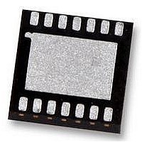
LM95214CISD National Semiconductor, LM95214CISD Datasheet - Page 17

LM95214CISD
Manufacturer Part Number
LM95214CISD
Description
SENSOR, TEMP, 4-DIODE, 2-WIRE I/F
Manufacturer
National Semiconductor
Datasheet
1.LM95214CISD.pdf
(38 pages)
Specifications of LM95214CISD
Ic Output Type
Current
Sensing Accuracy Range
± 1°C
Supply Current
0.57mA
Supply Voltage Range
3V To 3.6V
Resolution (bits)
11bit
Sensor Case Style
LLP
No. Of Pins
14
Svhc
No SVHC
Temperature Sensing Range
-40°C To +140°C
Rohs Compliant
Yes
Lead Free Status / RoHS Status
Lead free / RoHS Compliant
Available stocks
Company
Part Number
Manufacturer
Quantity
Price
Company:
Part Number:
LM95214CISD/NOPB
Manufacturer:
NS
Quantity:
8 157
Company:
Part Number:
LM95214CISDX/NOPB
Manufacturer:
14
Quantity:
4 211
1.12 SERIAL INTERFACE RESET
In the event that the SMBus Master is RESET while the
LM95214 is transmitting on the SMBDAT line, the LM95214
must be returned to a known state in the communication pro-
tocol. This may be done in one of two ways:
1.
2.
2.0 LM95214 Registers
Command register selects which registers will be read from or written to. Data for this register should be transmitted during the
Command Byte of the SMBus write communication.
When SMBDAT is LOW, the LM95214 SMBus state
machine resets to the SMBus idle state if either SMBDAT
or SMBCLK are held low for more than 35ms (t
Note that according to SMBus specification 2.0 all
devices are to timeout when either the SMBCLK or
SMBDAT lines are held low for 25-35ms. Therefore, to
insure a timeout of all devices on the bus the SMBCLK
or SMBDAT lines must be held low for at least 35ms.
When SMBDAT is HIGH, have the master initiate an
SMBus start. The LM95214 will respond properly to an
SMBus start condition at any point during the
(c) Serial Bus Read from a Register with the Internal Command Register preset to desired value.
(d) Serial Bus Write followed by a Repeat Start and Immediate Read
(b) Serial Bus Write to the Internal Command Register
P7
P6
FIGURE 8. SMBus Timing Diagrams
P5
TIMEOUT
Command Byte
).
P4
17
P3
1.13 ONE-SHOT CONVERSION
The One-Shot register is used to initiate a round of conver-
sions and comparisons when the device is in standby mode,
after which the device returns to standby. This is not a data
register and it is the write operation that causes the one-shot
conversion. The data written to this address is irrelevant and
is not stored. A zero will always be read from this register. All
the channels that are enabled in the Channel Enable Register
will be converted once and the TCRIT1, TCRIT2 and
TCRIT3 pins will reflect the comparison results based on this
round of conversion results of the channels that are not
masked.
communication. After the start the LM95214 will expect
an SMBus Address address byte.
P2
P1
P0
30006111
30006112
30006114
www.national.com


