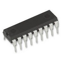
UC3903N UNITRODE, UC3903N Datasheet - Page 10

UC3903N
Manufacturer Part Number
UC3903N
Description
IC, SUPPLY/LINE MONITOR 18mA, 40V 18-DIP
Manufacturer
UNITRODE
Datasheet
1.UC3903N.pdf
(16 pages)
Specifications of UC3903N
Threshold Voltage
2.5V
No. Of Supervisors / Monitors
4
Supply Voltage Range
8V To 40V
Reset Type
Active-Low
Supply Current
18mA
Delay Time
30ms
Digital Ic Case Style
DIP
No. Of Pins
18
Lead Free Status / RoHS Status
Lead free / RoHS Compliant
Available stocks
Company
Part Number
Manufacturer
Quantity
Price
Company:
Part Number:
UC3903N
Manufacturer:
FAIR
Quantity:
1 000
Part Number:
UC3903N
Manufacturer:
TI/德州仪器
Quantity:
20 000
UC1903
UC2903
UC3903
SLUS233A – OCTOBER 1999 – REVISED SEPTEMBER 2008
OV and UV Comparators Maintain Accurate Thresholds
The structure of the OV and UV comparators, shown in
case where multiple sense inputs cross a fault threshold simultaneously. Unused sense inputs can be tied either
to the 2.5-V reference, or to another, utilized, sense input. The four under- and over-voltage sense inputs on the
UC1903 are clamped as detailed on the Sense 1 input in
Z1, prevent extreme under- and over-voltage conditions from inverting the outputs of the fault comparators. A
parasitic diode, D1, is present at the inputs as well. Under normal operation it is advisable to insure that voltage
levels at all of the sense inputs stay above –0.3 V. The same type of input protection exists at the line sense
input, Pin 15, except a 5-kΩ series resistor is used.
The fault delay circuitry on the UC1903 is also shown in
of the sense inputs Q20 is turned off, allowing the internal 60-mA current source to charge the user-selected
delay capacitor. When the capacitor voltage reaches 1.8 V, the OV and POWER OK outputs become active low.
When the fault condition goes away Q20 is turned back on, rapidly discharging the delay capacitor. Operation of
the under- voltage delay is, with appropriate substitutions, the same.
Start Latch and Supply Under-Voltage Sense Allow Predictable Power-Up
At power-Up, while the +V
V the POWER OK output will be driven low and the UV OV FAULT outputs are disabled. Once +V
the V
power up may be below the UVFAULT window and the UVFAULT output may be driven low.
10
A.
SUV
D1
Submit Documentation Feedback
UV COMPARATOR
The OV and UV comparators on the UC1903 trigger respective fault delay circuits when one or more of the sense
OV COMPARATOR
inputs move outside the fault window. Input clamps insure proper operation under extreme fault conditions.
Terminating the UV delay capacitor to VREF assures correct logic at power up.
threshold of 7 V the fault outputs will be enabled. As would be expected, the SENSE 1-4 voltages at
SENSE 1
SENSE 2
SENSE 3
SENSE 4
2 kW
5.7 V
R1
Z1
Q10
Q15
Q1
Q6
IN
input supply is below 3 V, all open collector outputs are off. With +V
Q11
Figure 8. OV and UV Comparators on the UC1903
Q2
Q16 Q17
Q7
Q12
Q3
Q8
Product Folder Link(s):
100 A
Q13
Q4
Q18
Q9
m
........................................................................................................................................
Q14
50 A
Q5
6.4 V
m
THRESHOLD
THRESHOLD
VOLTAGE
6.4 V
VOLTAGE
TO UV
TO OV
UC1903 UC2903 UC3903
Figure
Figure 8
Figure
HYSTERESIS
CONTROL
HYSTERESIS
CONTROL
8. In the case of an over-voltage condition at one
UV
8. The series 2-kΩ resistor, R1, and zener diode
OV
results in accurate fault thresholds even in the
Q19
Q20
6.4 V
Copyright © 1999–2008, Texas Instruments Incorporated
6.4 V
60 A
60 A
m
m
1.8 V
1.8 V
V
EXT.
UV DELAY
CAPACITOR
REF
EXT.
OV DELAY
CAPACITOR
IN
UV FAULT
INDICATION
TO OUTPUT
LOGIC
OV FAULT
INDICATION
TO OUTPUT
LOGIC
greater than 3
IN
rises above
www.ti.com


