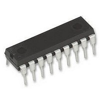
UC3903N UNITRODE, UC3903N Datasheet - Page 6

UC3903N
Manufacturer Part Number
UC3903N
Description
IC, SUPPLY/LINE MONITOR 18mA, 40V 18-DIP
Manufacturer
UNITRODE
Datasheet
1.UC3903N.pdf
(16 pages)
Specifications of UC3903N
Threshold Voltage
2.5V
No. Of Supervisors / Monitors
4
Supply Voltage Range
8V To 40V
Reset Type
Active-Low
Supply Current
18mA
Delay Time
30ms
Digital Ic Case Style
DIP
No. Of Pins
18
Lead Free Status / RoHS Status
Lead free / RoHS Compliant
Available stocks
Company
Part Number
Manufacturer
Quantity
Price
Company:
Part Number:
UC3903N
Manufacturer:
FAIR
Quantity:
1 000
Part Number:
UC3903N
Manufacturer:
TI/德州仪器
Quantity:
20 000
UC1903
UC2903
UC3903
SLUS233A – OCTOBER 1999 – REVISED SEPTEMBER 2008
Setting a Fault Window
The fault thresholds on the UC1903 are generated by creating positive and negative offsets, equal in magnitude,
that are referenced to the chip’s 2.5-V reference. The resulting fault window is centered around 2.5 V and has a
magnitude equal to that of the applied offsets. Simplified schematics of the fault window and reference circuits
are shown in
determined by the voltage applied at the window adjust pin, Pin 4. A bias cancellation circuit keeps the input
current required at Pin 4 low, allowing the use of a simple resistive divider off the reference to set the adjust pin
voltage.
The adjust voltage at Pin 4 is internally applied across R4, and an 8-kΩ resistor. The resulting current is mirrored
four times to generate current sources I
inputs are inside the fault window, a no-fault condition, Q4 and Q5 are turned on. In combination with D1 and D2
this prevents L
V
In terms of a sensed nominal voltage level, V
When a sense input moves outside the fault window given in
turns off Q4 or Q5. For the under-voltage case, Q5 is disabled and current source I
current through R7 becomes zero as I
overvoltage case is the same, with Q4 turning off, allowing I
result is a hysteresis at the sense inputs which is always 8% of the window magnitude. This is shown graphically
in
6
REF
Figure
Figure 2. Fault Window and Threshold Hysteresis Scale as a Function of the Voltage Applied at Pin 4
+ I
V ± 10 × V
2.5 V ±
S
OA
Submit Documentation Feedback
2.
(R5 + R6) and V
(
OB
Figure 1
V
ADJ
4
and L
ADJ
OD
)
%
along with the Typical Characteristics diagrams. The magnitude of the offsets is
from affecting the fault thresholds. In this case, the OV and UV thresholds are equal to
REF
OPERATION AND APPLICATION INFORMATION
– I
3.125
2.875
2.750
2.625
2.375
2.125
1.875
OC
2.25
2.5
(R7 + R8) respectively. The fault window can be expressed as:
3
2
Product Folder Link(s):
0
OB
No Fault
OA
Window Adjust Voltage (V
Fault
, I
cancels I
........................................................................................................................................
0.5
OB
S
, the window as a percent variation is:
, I
OC
Window
Fault
, and I
OC
1
Window
, giving an 8% reduction in the UV threshold offset. The
Fault
UC1903 UC2903 UC3903
OD
1.5
, all equal in magnitude. When all four of the sense
Equation
OD
ADJ
Hysteresis
to cancel the current flow, I
) at Pin 4
2
1, the appropriate hysteresis control signal
Copyright © 1999–2008, Texas Instruments Incorporated
2.5
25
20
15
10
5
0
-5
-10
-15
-20
-25
OB
flows through D2. The net
OA
, through R6. The
www.ti.com
(1)
(2)


