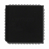
A3977SEDTR-T Allegro Microsystems Inc, A3977SEDTR-T Datasheet - Page 9

A3977SEDTR-T
Manufacturer Part Number
A3977SEDTR-T
Description
LEAD FREE A3977SEDTR
Manufacturer
Allegro Microsystems Inc
Datasheet
1.A3977SEDTR-T.pdf
(18 pages)
Specifications of A3977SEDTR-T
Rohs Compliant
YES
Applications
Stepper Motor Driver
Number Of Outputs
1
Current - Output
±2.5A
Voltage - Load
8 V ~ 35 V
Voltage - Supply
3 V ~ 5.5 V
Operating Temperature
-20°C ~ 85°C
Mounting Type
Surface Mount
Package / Case
44-LCC (J-Lead)
Motor Type
Stepper
No. Of Outputs
2
Output Current
2.5A
Output Voltage
35V
Supply Voltage Range
3V To 5.5V
Driver Case Style
LCC
No. Of Pins
44
Operating Temperature Range
-20°C To +85°C
Lead Free Status / RoHS Status
Lead free / RoHS Compliant
Other names
620-1146-2
A3977SEDTR-T
A3977SEDTR-T
Available stocks
Company
Part Number
Manufacturer
Quantity
Price
Company:
Part Number:
A3977SEDTR-T
Manufacturer:
ALLEGRO
Quantity:
1 500
Company:
Part Number:
A3977SEDTR-T
Manufacturer:
Allegro MicroSystems, LLC
Quantity:
10 000
A3977
Synchronous Rectifi cation. When a PWM off-cycle is
triggered by an internal fi xed off-time cycle, load current
will recirculate according to the decay mode selected by
the control logic. The A3977 synchronous rectifi cation fea-
ture will turn on the appropriate MOSFETs during the cur-
rent decay and effectively short out the body diodes with
the low r
signifi cantly and eliminate the need for external Schottky
diodes for most applications.
tive mode or disabled mode.
The synchronous rectifi cation can be set in either ac-
DS(on)
driver. This will reduce power dissipation
(T
A
= +25°C, V
A. Minimum Command Active Time
B. Minimum Command Active Time
C. Minimum STEP Pulse Width ...................... 1.0 μs
D. Minimum STEP Low Time ......................... 1.0 μs
E. Maximum Wake-Up Time ......................... 1.0 ms
Before Step Pulse (Data Set-Up Time) ..... 200 ns
After Step Pulse (Data Hold Time) ........... 200 ns
Microstepping DMOS Driver with Translator
Functional Description (cont’d)
DD
Timing Requirements
= 5 V, Logic Levels are V
Active Mode. When the SR input is logic low, active
mode is enabled and synchronous rectifi cation will occur.
This mode prevents reversal of the load current by turning
off synchronous rectifi cation when a zero current level is
detected. This prevents the motor winding from conduct-
ing in the reverse direction.
Disabled Mode. When the SR input is logic high, syn-
chronous rectifi cation is disabled. This mode is typically
used when external diodes are required to transfer power
dissipation from the A3977 package to the external diodes.
DD
and Ground)
115 Northeast Cutoff
1.508.853.5000; www.allegromicro.com
Allegro MicroSystems, Inc.
Worcester, Massachusetts 01615-0036 U.S.A.
9


