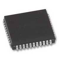
P89V51RB2FA NXP Semiconductors, P89V51RB2FA Datasheet - Page 32

P89V51RB2FA
Manufacturer Part Number
P89V51RB2FA
Description
MCU 8BIT 80C51 16K FLASH, PLCC44
Manufacturer
NXP Semiconductors
Datasheet
1.P89V51RC2FBC557.pdf
(80 pages)
Specifications of P89V51RB2FA
Controller Family/series
(8051) 8052
Core Size
8bit
No. Of I/o's
32
Program Memory Size
16KB
Ram Memory Size
1KB
Cpu Speed
40MHz
Oscillator Type
External Only
No. Of Timers
4
No. Of Pwm
RoHS Compliant
Available stocks
Company
Part Number
Manufacturer
Quantity
Price
Company:
Part Number:
P89V51RB2FA
Manufacturer:
NXP
Quantity:
1 000
Company:
Part Number:
P89V51RB2FA
Manufacturer:
NXP
Quantity:
2 000
Part Number:
P89V51RB2FA
Manufacturer:
NXP/恩智浦
Quantity:
20 000
Part Number:
P89V51RB2FA (FLA
Manufacturer:
NXP/恩智浦
Quantity:
20 000
Company:
Part Number:
P89V51RB2FA,529
Manufacturer:
NXP Semiconductors
Quantity:
10 000
Company:
Part Number:
P89V51RB2FAЈ¬529
Manufacturer:
NXP
Quantity:
150
NXP Semiconductors
P89V51RB2_RC2_RD2_5
Product data sheet
6.5.1 Capture mode
Table 21.
Table 22.
Not bit addressable; Reset value: XX00 0000B
Table 23.
In the Capture mode there are two options which are selected by bit EXEN2 in T2CON. If
EXEN2 = 0 Timer 2 is a 16-bit timer or counter (as selected by C/T2 in T2CON) which
upon overflowing sets bit TF2, the Timer 2 overflow bit.
The capture mode is illustrated in
Bit
4
3
2
1
0
Bit
7 to 2
1
0
Bit
Symbol
T2CON - Timer/counter 2 control register (address C8H) bit description
T2MOD - Timer 2 mode control register (address C9H) bit allocation
T2MOD - Timer 2 mode control register (address C9H) bit description
Symbol
TCLK
EXEN2
TR2
C/T2
CP/RL2
Symbol
-
T2OE
DCEN
7
-
Rev. 05 — 12 November 2009
6
-
Description
Transmit clock flag. When set, causes the UART to use Timer 2
overflow pulses for its transmit clock in modes 1 and 3. TCLK = 0
causes Timer 1 overflows to be used for the transmit clock.
Timer 2 external enable flag. When set, allows a capture or reload to
occur as a result of a negative transition on T2EX if Timer 2 is not
being used to clock the serial port. EXEN2 = 0 causes Timer 2 to
ignore events at T2EX.
Start/stop control for Timer 2. A logic ‘1’ enables the timer to run.
Timer or counter select. (Timer 2)
Capture/Reload flag. When set, captures will occur on negative
transitions at T2EX if EXEN2 = 1. When cleared, auto-reloads will
occur either with Timer 2 overflows or negative transitions at T2EX
when EXEN2 = 1. When either RCLK = 1 or TCLK = 1, this bit is
ignored and the timer is forced to auto-reload on Timer 2 overflow.
Description
Reserved for future use. Should be set to ‘0’ by user programs.
Timer 2 Output Enable bit. Used in programmable clock-out mode
only.
Down Count Enable bit. When set, this allows Timer 2 to be configured
as an up/down counter.
0 = internal timer (f
1 = external event counter (falling edge triggered; external clock’s
maximum rate = f
Figure
5
-
12.
osc
P89V51RB2/RC2/RD2
4
-
osc
/ 12
/ 6)
8-bit microcontrollers with 80C51 core
3
-
2
-
© NXP B.V. 2009. All rights reserved.
T2OE
1
…continued
DCEN
32 of 80
0


