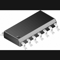
LMC6034IM National Semiconductor, LMC6034IM Datasheet - Page 5

LMC6034IM
Manufacturer Part Number
LMC6034IM
Description
Operational Amplifier (Op-Amp) IC
Manufacturer
National Semiconductor
Specifications of LMC6034IM
No. Of Amplifiers
4
Slew Rate
1.1V/µs
No. Of Pins
14
Peak Reflow Compatible (260 C)
No
Leaded Process Compatible
No
Mounting Type
Surface Mount
Package / Case
14-NSOIC
Lead Free Status / RoHS Status
Contains lead / RoHS non-compliant
Available stocks
Company
Part Number
Manufacturer
Quantity
Price
Company:
Part Number:
LMC6034IM
Manufacturer:
NS
Quantity:
10 990
Part Number:
LMC6034IM
Manufacturer:
NS/国半
Quantity:
20 000
Part Number:
LMC6034IM-TEL
Manufacturer:
NS/国半
Quantity:
20 000
Part Number:
LMC6034IMX
Manufacturer:
NS/国半
Quantity:
20 000
Company:
Part Number:
LMC6034IMX/NOPB
Manufacturer:
ST
Quantity:
7 733
Part Number:
LMC6034IMX/NOPB
Manufacturer:
TI/德州仪器
Quantity:
20 000
Typical Performance Characteristics
Output Characteristics
Current Sourcing
Open-Loop Frequency
Response
Stability vs
Capacitive Load
Note: Avoid resistive loads of less than 500 , as they may cause instability.
Applications Hint
Amplifier Topolgy
The topology chosen for the LMC6034, shown in Figure 1 , is
unconventional (compared to general-purpose op amps) in
that the traditional unity-gain buffer output stage is not used;
instead, the output is taken directly from the output of the in-
tegrator, to allow a larger output swing. Since the buffer tra-
ditionally delivers the power to the load, while maintaining
high op amp gain and stability, and must withstand shorts to
either rail, these tasks now fall to the integrator.
DS011134-33
DS011134-30
DS011134-27
Input Voltage Noise
vs Frequency
Frequency Response
vs Capacitive Load
Stability vs
Capacitive Load
V
5
S
=
As a result of these demands, the integrator is a compound
affair with an embedded gain stage that is doubly fed forward
(via C
driver. In addition, the output portion of the integrator is a
push-pull configuration for delivering heavy loads. While
sinking current the whole amplifier path consists of three
gain stages with one stage fed forward, whereas while
sourcing the path contains four gain stages with two fed
forward.
±
7.5V, T
DS011134-34
DS011134-28
f
DS011134-31
and Cff) by a dedicated unity-gain compensation
A
= 25˚C unless otherwise specified (Continued)
CMRR vs Frequency
Non-Inverting Large Signal
Pulse Response
www.national.com
DS011134-29
DS011134-32


