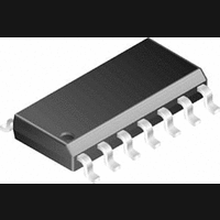
LMC6484IM National Semiconductor, LMC6484IM Datasheet - Page 4

LMC6484IM
Manufacturer Part Number
LMC6484IM
Description
Operational Amplifier (Op-Amp) IC
Manufacturer
National Semiconductor
Specifications of LMC6484IM
No. Of Amplifiers
4
Slew Rate
1.3V/µs
No. Of Pins
14
Amplifier Type
Operational
Mounting Type
Surface Mount
Peak Reflow Compatible (260 C)
No
Leaded Process Compatible
No
Number Of Channels
4
Voltage Gain Db
116.47 dB
Common Mode Rejection Ratio (min)
65 dB
Input Offset Voltage
3 mV at 5 V
Operating Supply Voltage
5 V, 9 V, 12 V, 15 V
Supply Current
2.8 mA at 5 V
Maximum Operating Temperature
+ 85 C
Package / Case
SOIC-14 Narrow
Minimum Operating Temperature
- 40 C
Lead Free Status / RoHS Status
Contains lead / RoHS non-compliant
Available stocks
Company
Part Number
Manufacturer
Quantity
Price
Company:
Part Number:
LMC6484IM
Manufacturer:
NS
Quantity:
16 600
Part Number:
LMC6484IM
Manufacturer:
NS/国半
Quantity:
20 000
Part Number:
LMC6484IMX
Manufacturer:
NS/国半
Quantity:
20 000
Company:
Part Number:
LMC6484IMX/NOPB
Manufacturer:
NS
Quantity:
1 000
Part Number:
LMC6484IMX/NOPB
Manufacturer:
TI/德州仪器
Quantity:
20 000
www.national.com
Symbol
Symbol
T.H.D.
V
TCV
I
I
CMRR
PSRR
V
V
I
SR
GBW
T.H.D.
Symbol
B
OS
S
Unless otherwise specified, all limits guaranteed for T
limits apply at the temperature extremes.
Unless otherwise specified, all limits guaranteed for T
Unless otherwise specified, V
OS
CM
O
AC Electrical Characteristics
DC Electrical Characteristics
AC Electrical Characteristics
Note 1: Absolute Maximum Ratings indicate limits beyond which damage to the device may occur. Operating Ratings indicate conditions for which the device is in-
tended to be functional, but specific performance is not guaranteed. For guaranteed specifications and the test conditions, see the Electrical Characteristics.
Note 2: Human body model, 1.5 k
OS
Total Harmonic Distortion
Input Offset Voltage
Input Offset Voltage
Average Drift
Input Bias Current
Input Offset Current
Common Mode
Rejection Ratio
Power Supply
Rejection Ratio
Input Common-Mode
Voltage Range
Output Swing
Supply Current
Slew Rate
Gain-Bandwidth Product
Total Harmonic Distortion
Parameter
Parameter
Parameter
+
in series with 100 pF. All pins rated per method 3015.6 of MIL-STD-883. This is a class 2 device rating.
= 3V, V
0V
3V
For CMRR
R
R
All Four Amplifiers
L
L
= 2 k
= 600
−
f = 1 kHz, A
R
f = 10 kHz, A
R
V
V
V
+
= 0V, V
L
L
(Note 11)
f = 10 kHz, A
R
CM
+
Conditions
= 10V
= 10 k , V
= 10 k , V
L
= 10 k , V
15V, V
to V
to V
Conditions
3V
Conditions
50 dB
CM
(Continued)
+
+
/2
V
/2
= V
−
V
J
J
= −2
O
O
= 0V
V
= 25˚C, V
= −2
= 25˚C, V
O
O
= 4.1 V
= 8.5 V
= −2
= V
= 2 V
+
/2 and R
4
PP
PP
PP
+
+
V
V
(Note 5)
−
+
= 5V, V
= 3V, V
0.02
0.01
0.37
1.65
Typ
0.9
2.0
− 0.25
+ 0.25
2.8
0.2
2.7
74
80
(Note 5)
(Note 5)
0.01
0.01
Typ
L
0.01
Typ
0.9
1.0
>
−
−
1M
= 0V, V
= 0V, V
LMC6484AI
(Note 6)
LMC6484A
LMC6484AI
Limit
(Note 6)
2.0
2.7
2.5
0.6
2.5
3.0
(Note 6)
V
64
68
0
Limit
Limit
+
CM
CM
= V
= V
O
O
LMC6484I
= V
= V
(Note 6)
LMC6484I
LMC6484I
(Note 6)
Limit
(Note 6)
3.0
3.7
2.5
0.6
2.5
3.0
Limit
60
60
V
+
+
0
Limit
/2 and R
/2 and R
+
LMC6484M
L
L
LMC6484M
LMC6484M
(Note 6)
>
>
(Note 6)
Limit
(Note 6)
Limit
3.0
3.8
2.5
0.6
2.5
3.2
1M. Boldface
1M
60
60
V
Limit
0
+
Units
µV/˚C
Units
max
max
max
max
Units
min
min
min
min
mV
mA
V/µs
MHz
pA
pA
dB
dB
V
V
V
V
V
V
%
%
%


