MCP1630RD-DDBK1 Microchip Technology, MCP1630RD-DDBK1 Datasheet - Page 13
MCP1630RD-DDBK1
Manufacturer Part Number
MCP1630RD-DDBK1
Description
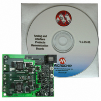
MCP1630 Dual Synchronous Buck Regulator Demo Board DEVTOOL - Analog
Manufacturer
Microchip Technology
Type
DC/DC Switching Converters, Regulators & Controllersr
Specifications of MCP1630RD-DDBK1
Main Purpose
DC/DC, Step Down
Outputs And Type
2, Non-Isolated
Voltage - Output
1.22 ~ 2.3V, 2.42 ~ 3.39V
Current - Output
20A, 20A
Voltage - Input
9 ~ 13.5V
Regulator Topology
Buck
Frequency - Switching
500kHz
Board Type
Fully Populated
Utilized Ic / Part
MCP1630
Input Voltage
12 V
Interface Type
Ethernet
Product
Power Management Modules
Lead Free Status / RoHS Status
Lead free / RoHS Compliant
Power - Output
-
Lead Free Status / Rohs Status
Lead free / RoHS Compliant
For Use With/related Products
MCP1630
Lead Free Status / RoHS Status
Lead free / RoHS Compliant, Contains lead / RoHS non-compliant


© 2008 Microchip Technology Inc.
2.3.3
1. The MCP1630 Dual Buck Reference Design can be programmed to calibrate
2. To enter the programming mode, apply input voltage within the specified
3. Once in Programming mode, the first variable to set is V
4. Press M once to select V
5. Press M once to select between output sequencing or tracking. D1 flashing
6. Press M once to select between frequency dithering on and frequency dithering
7. By pressing and holding the M button, the selected settings will be programmed.
FIGURE 2-1:
Note:
Note:
V
on or off.
operating range (9V to 13.5V). Press and hold the M (SW1) button. While still
holding the M button, press and release the on/off (SW3) button. The flashing
rate of LED D1 should increase, indicating Programming mode.
S button to increase V
it wraps around to the minimum setting.
similar to setting V
indicates that sequencing is selected. Press M to change from sequencing to
tracking, or from tracking to sequencing.
off. D1 flashing indicates that frequency dithering is selected.
The next power-up cycle for the converter will return to the programmed settings.
OUT1
, V
Programming
The range of V
R
(maximum).
The range of V
R
(maximum).
10
42
OUT2
. The range of V
. The range of V
, output sequencing or tracking and switching frequency dithering
Mode, Select and On/Off Switch Location.
OUT1
OUT1
OUT2
OUT1
.
OUT2
is controlled by the value of fixed resistors R
is controlled by the value of fixed resistors R
OUT1
OUT2
. Keep pressing the S button to increase V
Installation and Operations
. V
is typically from 2.42V (minimum) to 3.39V
is typically from 1.22V (minimum) to 2.3V
OUT2
in increased by pressing the S button
OUT1
. Press the select
DS51531B-page 9
Mode
OUT1
34
14
Select
On/Off
, R
, R
35
15
until
and
and
Related parts for MCP1630RD-DDBK1
Image
Part Number
Description
Manufacturer
Datasheet
Request
R

Part Number:
Description:
REF DESIGN MCP1630 NIMH BATT CHG
Manufacturer:
Microchip Technology
Datasheet:

Part Number:
Description:
BOARD DEMO FOR MCP1630 LI-ION
Manufacturer:
Microchip Technology
Datasheet:

Part Number:
Description:
REF DESIGN MCP1630V BI-DIR 4CELL
Manufacturer:
Microchip Technology
Datasheet:

Part Number:
Description:
REFERENCE DESIGN FOR MCP1630
Manufacturer:
Microchip Technology
Datasheet:
Part Number:
Description:
Power Management IC Development Tools MCP1630 Sepic Automotive LED Drvr
Manufacturer:
Microchip Technology
Datasheet:

Part Number:
Description:
Manufacturer:
Microchip Technology Inc.
Datasheet:
Part Number:
Description:
Manufacturer:
Microchip Technology Inc.
Datasheet:
Part Number:
Description:
Manufacturer:
Microchip Technology Inc.
Datasheet:
Part Number:
Description:
Manufacturer:
Microchip Technology Inc.
Datasheet:
Part Number:
Description:
Manufacturer:
Microchip Technology Inc.
Datasheet:
Part Number:
Description:
Manufacturer:
Microchip Technology Inc.
Datasheet: