C320PRP2 EATON CUTLER HAMMER, C320PRP2 Datasheet - Page 31
C320PRP2
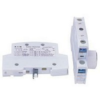
Manufacturer Part Number
C320PRP2
Description
Double Power Pole
Manufacturer
EATON CUTLER HAMMER
Datasheet
1.A202K2CXM.pdf
(40 pages)
Specifications of C320PRP2
For Use With
C30CN Lighing Contactors


June 2008
Figure 37-13. Electrically Held Combination Contactors — CN35
CA08102001E
1
2/13
Not for use with
auto reset OL relays.
Yellow
Red
3/14
START/STOP Selector Switch
Black
CPT
Fusible
Control
Transformer
(If Used)
See Figure 2
START/STOP Pushbuttons
2-Wire Control
3
4
Connector
If Figure 2
Omit This
Is Used
Stop (OFF)
Start (ON)
Figure A
1
Figure B
1
3
1
2
3/14
1
Black 3/14
Start (ON)
Red
4
2
L1
L1
T1
1
2
Red
Disconnecting
D.S. or C.B
A1
Means
3-Wire Control
1
Front View Diagram
T2
Start
L2
L2
3
4
Stop
A2
”C“
Figure 1
2-Position Selector Switch
Remote Control
1
2
3
4
3/14
2/13
1
T3
L3
L3
5
6
Figure D
Yellow
Hand
3
3
4
4
When more than one pushbutton
station is used, omit connector ”A“
and connect per sketch below.
3-Position Selector Switch
2/13
3/14
For more information visit: www.eaton.com
Yellow
Hand
Black
Auto
Red
Black
Red
Auto
Lighting Contactors
UL Rated AC Contactors
Wiring Diagrams
Start
Stop
3/14
Local Control
(Flange-Mounting
If Used)
See Figures
A,B,C, D, E and F
1
Figure C
1
Remote Switch
3/14
”A“
Local Control
Pilot Light (Motor RUN)
Start
Stop
To Coil
Terminal ”A1“
Figure E
X2
X1
”A1“ and ”A2“
Coil Terminals
Connect to
3/14
2/13
1
Black/White
Black/White
Remote
Start
Stop
Fusible Control Transformer
Combined Remote and Local
STOP/START with Pilot Light
Connector
For Figures 1 and 2
2/13
Stop (OFF)
Start (ON)
Omit
Figure 2
4
2
Figure F
3
1
L1
Connections
X1
X2
1
Stop (OFF)
Secondary
Start (ON)
4
2
Local
A1
”A1“ and ”A2“
Connections
Coil Terminals
3
Connect to
1
L2
Primary
3
Black/White
Black/White
260880 D4
A2
2/13
3/14
3/14
1
L3
5
1
37-31
37
Related parts for C320PRP2
Image
Part Number
Description
Manufacturer
Datasheet
Request
R

Part Number:
Description:
PROGRAMMABLE LOGIC CONTROLLER
Manufacturer:
EATON CUTLER HAMMER
Part Number:
Description:
Pm Power Pro 3000/5000 A-B Accel/On Interface
Manufacturer:
EATON CUTLER HAMMER
Part Number:
Description:
Handle Tie Bar For (2) - 1 Pole Type BR Breakers
Manufacturer:
EATON CUTLER HAMMER
Part Number:
Description:
Type CH Breaker 150A/2 Pole 120/240V 10K
Manufacturer:
EATON CUTLER HAMMER
Part Number:
Description:
Tenant Branch Breaker 125A/3 Pole 120/240V 42K
Manufacturer:
EATON CUTLER HAMMER
Part Number:
Description:
Type CL Breaker 25A/1Pole 120/240V 10K-Classified 1" Ckt Bkr
Manufacturer:
EATON CUTLER HAMMER
Part Number:
Description:
FD BREAKER 1P 80 AMP WITH LOAD ONLY TERMINALS
Manufacturer:
EATON CUTLER HAMMER
Part Number:
Description:
GD 2 POLE BREAKER, 25 AMP, SINGLE PACKED
Manufacturer:
EATON CUTLER HAMMER
Part Number:
Description:
Handle Tie Bar For (2) - 1 Pole Type BR Breakers
Manufacturer:
EATON CUTLER HAMMER
Part Number:
Description:
Type CL Breaker 25A/1Pole 120/240V 10K-Classified 1" Ckt Bkr
Manufacturer:
EATON CUTLER HAMMER