C320PRP2 EATON CUTLER HAMMER, C320PRP2 Datasheet - Page 32
C320PRP2
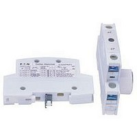
Manufacturer Part Number
C320PRP2
Description
Double Power Pole
Manufacturer
EATON CUTLER HAMMER
Datasheet
1.A202K2CXM.pdf
(40 pages)
Specifications of C320PRP2
For Use With
C30CN Lighing Contactors


37
37-32
Figure 37-14. Magnetically Latched Combination Contactors
Black
White
START/STOP Selector Switch
START/STOP Pushbuttons
Red
Black
Yellow
1
3
2
Lighting Contactors
UL Rated AC Contactors
Wiring Diagrams
1
Auxiliary Contact
2
3
2
1
(When Used)
Pilot Light (ON)
Auxiliary
X2
Figure A
X1
Figure C
Contact
Stop (OFF)
Figure B
Start (ON)
NC
Top
3
3
3
3
4
Black/White
Black/White
Yellow
Connect to Terminals
Red
(OFF)
Stop
NO
Black
4
4
2
Start
(ON)
Red
”3“ and ”L2“
Red
1
2
3
3
L2
L1
L1
Disconnecting
ON
Poles to Load
Front View Diagram
D.S. or C.B
Local Control
Means
M
L2
L2
Figure 1
OFF
L3
L3
CPT
Fusible
Control
Transformer
(If Used)
See Figure 2
START/STOP with Pilot Light
For more information visit: www.eaton.com
Auxiliary Contact
Stop (OFF)
Module
Control
Start (ON)
4
4
(When Used)
+
Pilot Light (OFF)
–
”C“
L2
3
3
Red
Figure D
X2
X1
Figure E
X2
X1
Black/White
Black/White
”2“ and ”L2“
Connect to
”3“ and ”L2“
Terminals
Connect to
Black/White
Black/White
Terminals
Local
Control
(Flange-
Mounting
If Used)
See
Figures
A,B,C,
D and E
2
L2
3
2
1
Connections for
Dual Voltage Rated
Transformer – See
Transformer Nameplate
Remove wire ”C“ (Figure 1) if used and connect as shown
below. (All other starter wires remain as shown in Figure 1).
Lines
1
OFF
OFF
Momentary
Pushbutton
L1
L2
L3
Pushbutton
Maintained
Voltage
Control
Line
1
1
ON
ON
Fusible Control Transformer
D.S.
C.B.
or
Elementary Diagram
Remote Control
3-Wire Control
3
2
Top
Figure 2
NO
Start
Stop
NC
L1
1
Connections
L1
L2
L3
Secondary
L2
3
Black
Red
ON
M
3
2
1
L3
Red
5
M
M
M
White
Connections
Voltage
Control
Primary
Line
Module
Control
+
–
260887 D4
OFF
CA08102001E
”C“
M
+
–
June 2008
Red
L2
Load
L2
Related parts for C320PRP2
Image
Part Number
Description
Manufacturer
Datasheet
Request
R

Part Number:
Description:
PROGRAMMABLE LOGIC CONTROLLER
Manufacturer:
EATON CUTLER HAMMER
Part Number:
Description:
Pm Power Pro 3000/5000 A-B Accel/On Interface
Manufacturer:
EATON CUTLER HAMMER
Part Number:
Description:
Handle Tie Bar For (2) - 1 Pole Type BR Breakers
Manufacturer:
EATON CUTLER HAMMER
Part Number:
Description:
Type CH Breaker 150A/2 Pole 120/240V 10K
Manufacturer:
EATON CUTLER HAMMER
Part Number:
Description:
Tenant Branch Breaker 125A/3 Pole 120/240V 42K
Manufacturer:
EATON CUTLER HAMMER
Part Number:
Description:
Type CL Breaker 25A/1Pole 120/240V 10K-Classified 1" Ckt Bkr
Manufacturer:
EATON CUTLER HAMMER
Part Number:
Description:
FD BREAKER 1P 80 AMP WITH LOAD ONLY TERMINALS
Manufacturer:
EATON CUTLER HAMMER
Part Number:
Description:
GD 2 POLE BREAKER, 25 AMP, SINGLE PACKED
Manufacturer:
EATON CUTLER HAMMER
Part Number:
Description:
Handle Tie Bar For (2) - 1 Pole Type BR Breakers
Manufacturer:
EATON CUTLER HAMMER
Part Number:
Description:
Type CL Breaker 25A/1Pole 120/240V 10K-Classified 1" Ckt Bkr
Manufacturer:
EATON CUTLER HAMMER